elec-rec
Pictures
 |
 |
 |
Source
elec-rec firmware: https://github.com/vsergeev/elec-rec
elec-rec schematic: https://github.com/vsergeev/elec-rec/raw/master/hardware/elec-rec.sch
elec-rec board layout: https://github.com/vsergeev/elec-rec/raw/master/hardware/elec-rec.brd
Concept
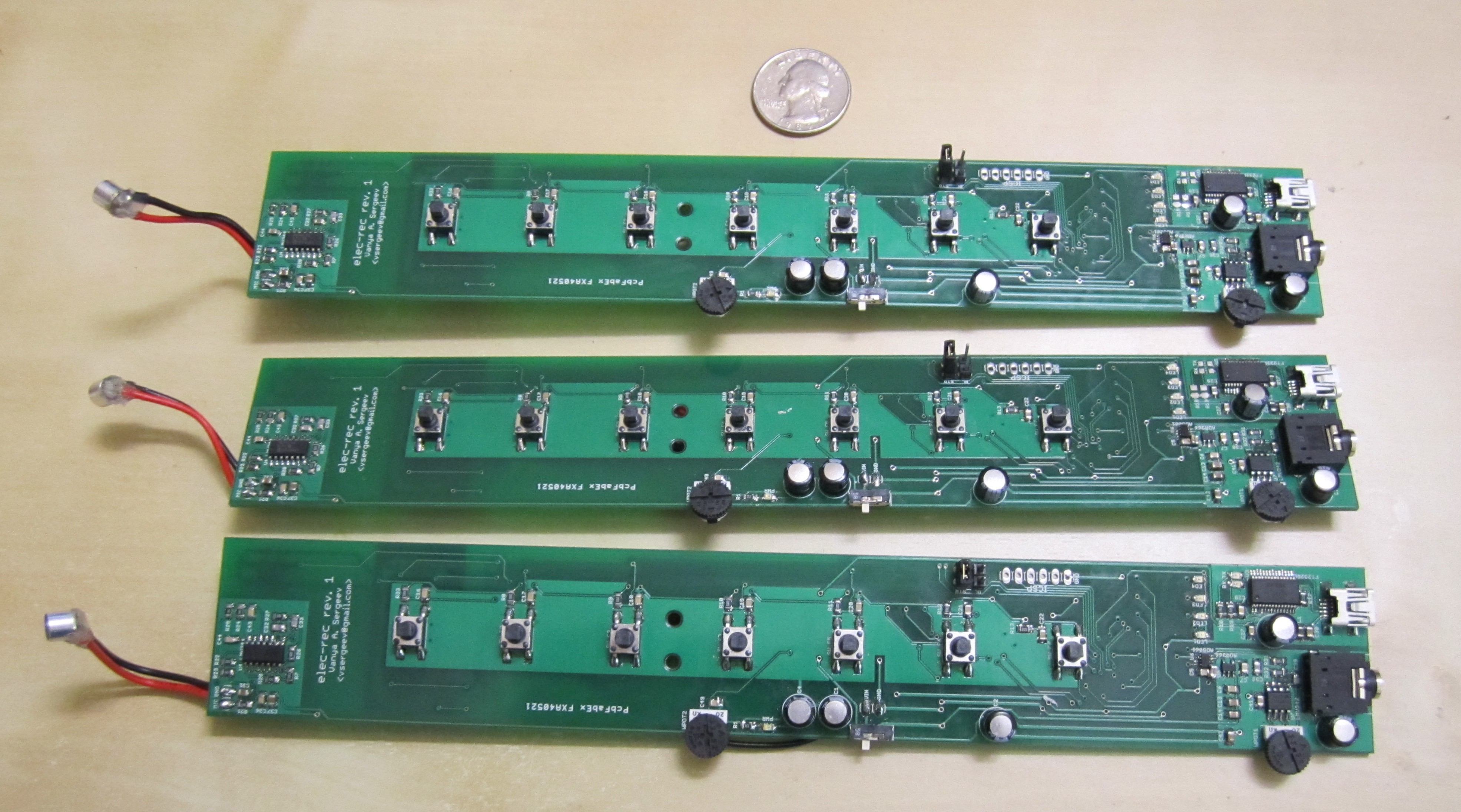
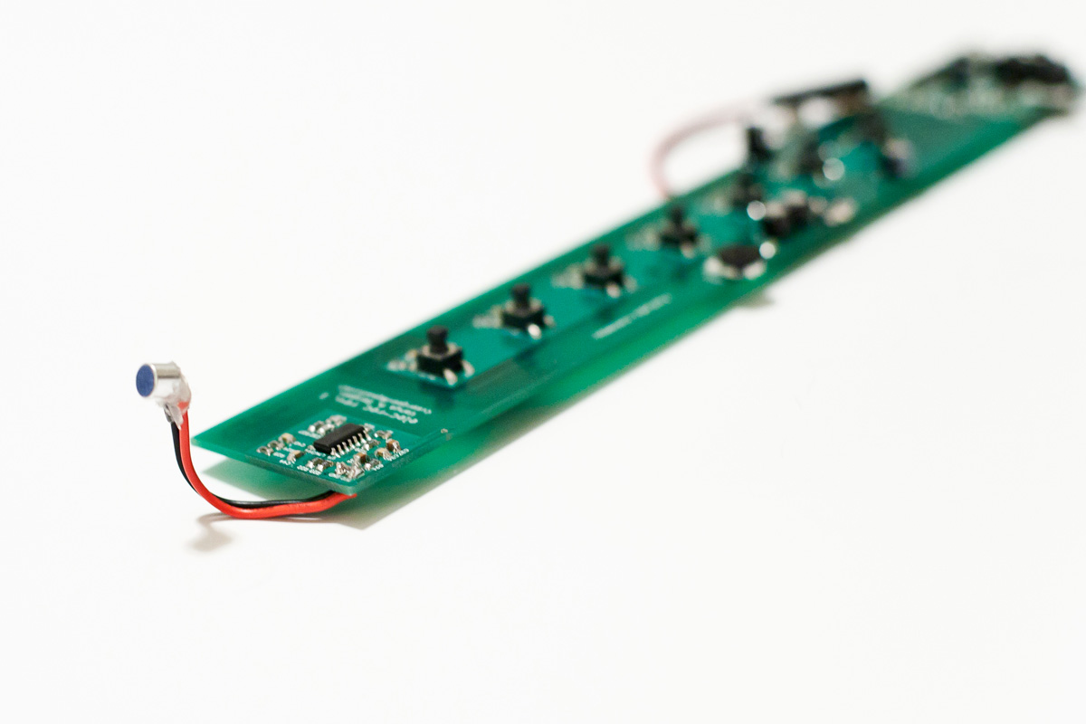
The Electronic Recorder (elec-rec) is an open hardware, open source electronic wind instrument. At a first glance, the elec-rec is comprised of a breath input provided by an electret microphone, push button inputs to control sound pitch, a microcontroller to process the inputs and synthesize audio, a 3.5mm jack for audio output, and a USB port for configuration. It supports battery power, meaning it can be used as a standalone instrument. I call it the elec-rec because its interface basically emulates a recorder’s interface; in fact, the seven push buttons used to select pitch are spaced identically to recorder pitch holes.
The motivation behind the elec-rec was to create an electronic musical instrument with a flute or recorder-like interface, but with the reconfigurability and processing potential of electronic hardware to support features like multiple instruments and polyphony. A side goal was to make the device inexpensive, just like a multitude of other wind instruments such as recorders, ocarinas, tin whistles, and pan flutes. Many of these can be had for as little as ten dollars, take a lifetime to master, and in the hands of a professional produce music that prove the instrument is much more than the sum value of its parts. The elec-rec currently costs about $50 in parts in low quantities, plus the cost of fabricating the PCB. The elec-rec is open source, in all aspects: hardware, firmware, and software.
The elec-rec hardware platform is very general, and might be better thought of as a generic sampled-data system with an analog input (microphone), digital inputs (buttons), processing stage, and analog output (mono audio). The particular firmware I’ve written yields a simple reconfigurable tonal wind instrument with several features, but the platform is general enough to support a vocoder, noise instrument, etc. with simply a change of firmware.
Hardware and Schematic
                          elec rec hardware block diagram

       +----------------+  +---------------+  +--------------+  +-------------+
       | Digital Input  |  | Digital Input |  | Analog Input |  |Accelerometer|
       | 7 Front Buttons|  | 4 Back Buttons|  | Wheel Pot    |  | (Unmounted) |
       +------------+---+  +---+-----------+  +----------+---+  +---+---------+
                    |          |                         |          |
                    |          +--------+   +------------+          |
                    +---------------+   |   |   +-------------------+
                                    |   |   |   |
                                    v   v   v   v
+------------+   +-----------+   +----------------+   +--------+   +----------------+   +--------+
|            |   |AC Coupling|   |                |   |        |   |LPF             |   | 3.5mm  |
| Microphone +-->|Gain       +-->|  LPC1313 MCU   +-->| 16 bit +-->|Volume Wheel Pot+-->| Stereo |
|   Input    |   |LPF        |   | ARM Cortex M3  |   |  DAC   |   |Buffer          |   | Output |
|            |   +-----------+   |                |   |        |   |AC Coupling     |   +--------+
+------------+                   +--+-------------+   +--------+   +----------------+
                                    |       ^   ^
                        +-----------+       |   |
                        |                 +-+   +------+
                        |                 |            |
                        v                 v            v
                   +--------+      +------------+  +--------+   +--------+
                   |4 Status|      |Non volatile|  |UART/USB+-->|USB Port|
                   |  LEDs  |      |   Memory   |  | Bridge |   | Mini-B |
                   +--------+      +------------+  +--------+   +--------+

vsergeev
(to be generated with ditaa)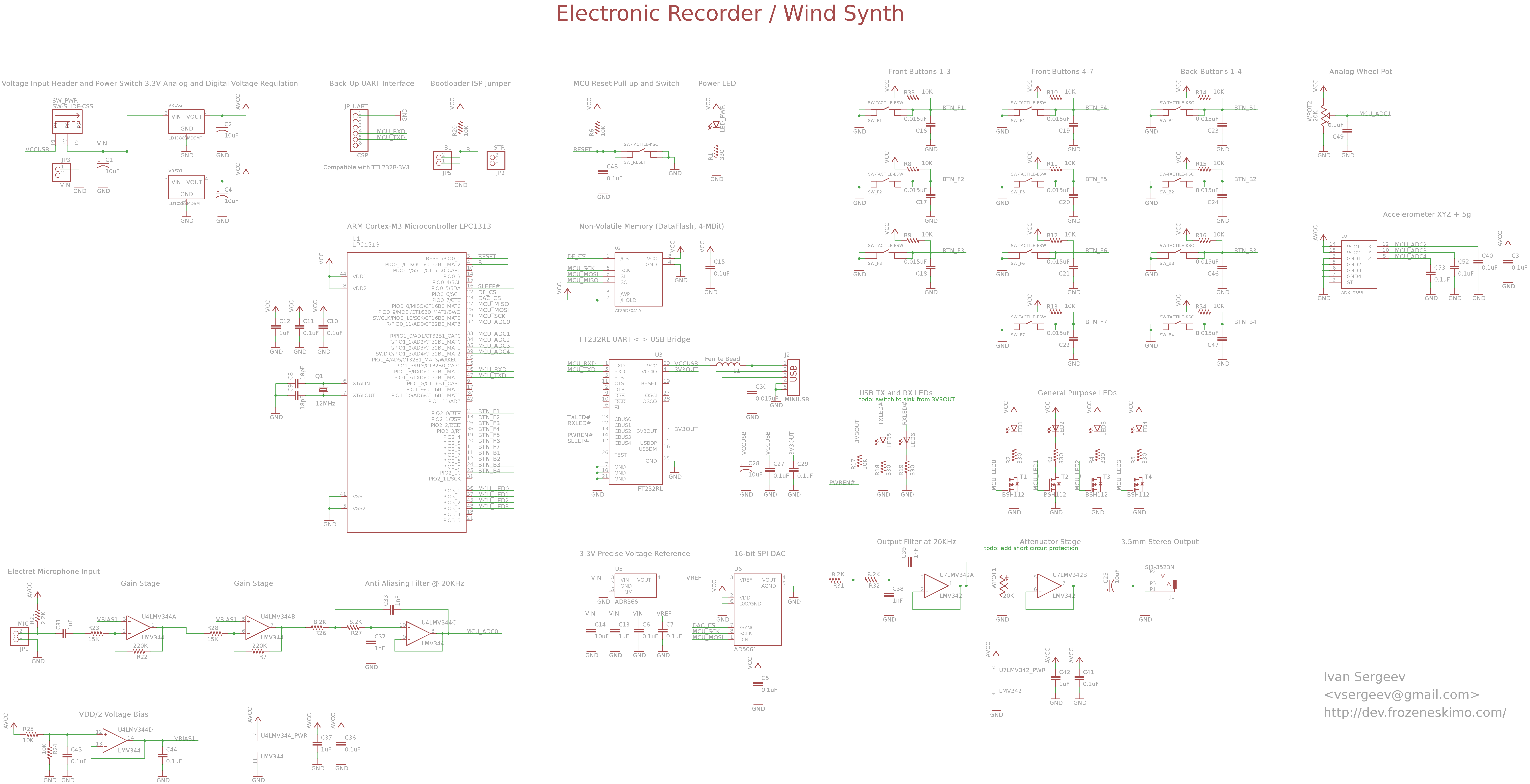 |
Brief Description of Major Stages
The input stage is responsible for amplifying and filtering the microphone input before it is sampled at the microcontroller’s ADC input. The digital stage consists of a microcontroller for inputs processing and sound synthesis, non-volatile memory for sound waveform storage, and a UART/USB bridge for communication with a host computer for flashing and waveform uploading. The output stage consists of a DAC to produce the analog waveform, a smoothing filter, a potentiometer attenuator for volume control, and outputs to a standard 3.5mm stereo jack.
For the analog stages, I used Microchip MCP6024 op-amps. They are a bit pricey, but are rail-to-rail input and output and have some other great specs: 10MHz GBW, 7V/uS slew, 500uV offset.
Analog Input Stage:
- Electret Microphone
- AC coupling capacitor
- Two inverting gain stages
- Second-order anti-aliasing filter at about 20KHz
Digital / Processing Stage:
- NXP LPC1313 Cortex M3 microcontroller
- Atmel DataFlash 4-Mbit non-volatile memory
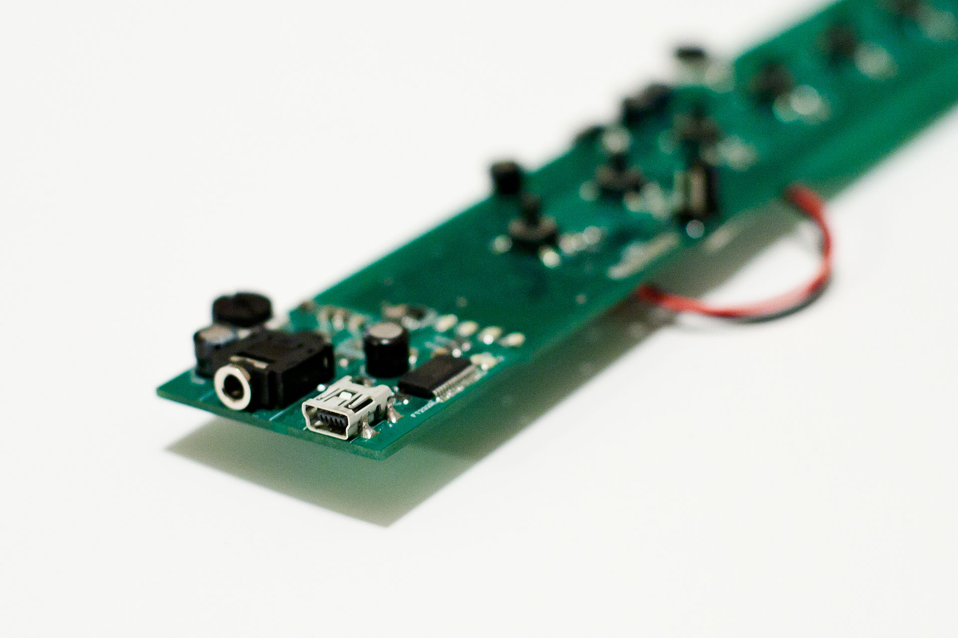
- FT232RL UART/USB bridge IC, mini-B USB port
Analog Output Stage:
- AD5061 16-bit SPI DAC
- ADR366 3.3V voltage reference for the DAC
- Second-order smoothing filter at about 20KHz
- Wheel potentiometer attenuator for volume control
- Op-amp buffer
- AC coupling capacitor
- 3.5mm output jack
Buttons and Other Inputs:
- 7 top push buttons for pitch (with RC filters for debouncing)
- 4 back push buttons for control/configuration (with RC filters for debouncing)
- 1 back push button for reset (with RC filter for debouncing)
- 1 analog wheel pot for an additional continuous input
Power:
- Two ST LD1086 3.3V voltage regulators provide the analog and digital rails
- Power switch to select power input between external/battery and USB
Miscellaneous:
- 1 power indicator LED
- 4 general purpose LEDs
- Pads on the board to support an ADXL335 accelerometer. (The accelerometer was not mounted in the elec-rec demonstrated here.)
Parts List
| Name | Digi-Key PN | Price | Part Reference | Brief Description |
|---|---|---|---|---|
| ICs | ||||
| LPC1313 | 568-4914-ND | $3.50 | U1 | ARM Cortex M3 MCU by NXP |
| LD1086 | 497-3446-1-ND | $1.73 x 2 | VREG1,VREG2 | 3.3V Linear Voltage Regulator |
| AD5061 | AD5061BRJZ-2REEL7CT-ND | $6.78 | U6 | 16-bit DAC (4us settle) |
| ADR366 | ADR366AUJZ-R2CT-ND | $2.08 | U5 | 3.3V Voltage Reference for DAC |
| AT25DF041A | AT25DF041A-SSH-B-ND | $1.08 | U2 | 4-MBit 70MHz Atmel DataFlash |
| FT232RL | 768-1007-1-ND | $4.50 | U3 | USB to UART bridge |
| LMV344 | 296-20925-1-ND | $0.95 | U4 | Filtering op-amps (Quad, 1MHz GBW, 1V/uS) |
| LMV342 | LMV342MA-ND | $1.12 | U7 | Filtering op-amps (Dual, 1MHz GBW, 1V/uS) |
| Ports and Jacks | ||||
| USB mini-B Port | H2959CT-ND | $1.18 | J2 | USB mini-B socket |
| Audio Jack | CP1-3523N-ND | $1.02 | J1 | 3.5mm Stereo female jack (3 conductors / 3 contacts, no switch) |
| Buttons and Switches | ||||
| SW Front | EEG1869CT-ND | $0.52 x 7 | SW_F1,SW_F2,SW_F3, SW_F4,SW_F5,SW_F6, SW_F7 |
7 front push buttons |
| SW Back | 401-1757-1-ND | $0.72 x 5 | SW_B1,SW_B2,SW_B3, SW_B4,SW_RESET |
4 back push buttons and reset button |
| SW Power | 563-1090-ND | $0.68 | SW_PWR | Power slide switch |
| Wheel Pots | 3352T-203LF-ND | $1.58 x 2 | WPOT1,WPOT2 | 2 Wheel pots (one volume, one analog input) |
| Passives | ||||
| 12MHz Crystal | 535-10218-1-ND | $0.41 | Q1 | 12MHz Crystal |
| Passives | Misc. | $6.10 | Passives | |
| Misc. | ||||
| Lite-On Green LED | 160-1423-1-ND | $0.44 x 4 | LED1,LED2,LED3,LED4 | 4 Status LEDs (Green) |
| Lite-On Amber LED | 160-1419-1-ND | $0.44 x 2 | LED5,LED6 | 2 FT232RL TX/RX LEDs (Orange) |
| Lite-On Red LED | 160-1176-1-ND | $0.40 | LED_PWR | Power LED (Red) |
| BSH112 | 568-1768-1-ND | $0.32 x 4 | T1,T2,T3,T4 | FETs for driving LEDs |
| Microphone | 102-1732-ND | $2.28 | MIC | Electret Microphone (100Hz-20KHz) |
| ADXL325B | ADXL325BCPZ-RL7CT-ND | $4.82 | XYZ +-5g Accelerometer | |
| Total | $51.47 |
Firmware
As I’ve mentioned above, some of the choices made in the firmware were design decisions to yield a simple reconfigurable tonal instrument, but are completely arbitrary as far as the hardware platform is concerned. In other words, this firmware is just one approach to processing the inputs and generating the outputs on the elec-rec hardware.
The elec-rec firmware was written in C, and uses the CMSIS abstraction layer. Check out my guide and thoughts on CMSIS here: Getting Started with Cortex M3, CMSIS, and GNU Tools
In instrument mode, the heart of the elec-rec firmware is an interrupt-driven (by the Cortex M3 SysTick timer) periodic sample, process, and write handler that runs at 36KHz. This main handler is SysTick_Handler() in main.c. In this handler:
- digital I/O buttons are read and debounced (across multiple timer ticks)
- a new microphone sample is read if one is available, and the ADC sampling is restarted
- existing microphone samples are progressed through the digital microphone filter
- samples from enabled cached multi-notes waveforms are combined additively in a sample mixer
- the latest sound sample corresponding to the current fingering is fetched from external non-volatile memory
- the sound sample is copied into an unused multi-note waveform buffer in microcontroller RAM and the state machine governing this buffer is updated, in case the user wishes to designate this note as a sustained multi-note in the near future
- the sound sample is adjusted in volume by the filtered microphone value and added to the sample mixer
- the sampler mixer is written to DAC
The elec-rec firmware supports four different instrument banks, which can be selected via a configuration button mechanism described in the usage manual below. The four status LEDs reflect the currently selected instrument bank.
Multi-note is a feature that allows for multiple sustained notes to be played concurrently alongside the active note. The instrument’s volume is split halfway between the background multi-notes and the current active note. Since fetching each sample from external memory for all four multi-notes in addition to the active note (up to 5 sample fetches) is too expensive in terms of time for the 36KHz periodic sampling/writing interval, active notes are cached in multi-note waveform buffers in the microcontroller’s on-board RAM. A configuration button mechanism can then enable the active note as a multi-note, or reset and disable all multi-notes.
In controller and data modes, the periodic sampling / writing handler is suspended and instead Controller_loop() or Data_loop() are run, respectively. The controller mode of the elec-rec simply prints all inputs continuously in an easily parsable ASCII format to the serial port. The data mode of the elec-rec accepts instructions over the serial port to rewrite the non-volatile memory to update the instrument bank waveforms. See the usage manual below for more information on controller and data modes.
The microphone is digitally rectified and filtered aggressively to yield an amplitude peak detector that can be used as a reliable breath input. Currently, the raw microphone data is passed through a 4th-order EWMA filter, then passed through a bounder / limiter and scaled by the microphone calibration variable, then passed through a 3rd-order EWMA filter. I experimented a while with some basic FIR filters, which worked well, but were too computationally expensive to meet the timing on 36KHz periodic sampling / writing handler (leading to audible audio distortion).
Necessary in the elec-rec code base are also SPI-based drivers written for the Atmel AT25DF041A DataFlash, and the Analog Devices AD5061 DAC.
The elec-rec is easily flashed over the same USB serial port that is used in controller and data modes. Installing the bootloader jumper and resetting the elec-rec causes the microcontroller to boot its flashing bootloader ROM, and the microcontroller can then be flashed over the USB serial port with a tool like Flash Magic.
Storage of Waveforms on Non-Volatile Memory
The non-volatile flash memory is programmed in data mode, and later read in instrument mode, with the following layout:
Origin at 0x0

# Bytes |	Description
-------------------------------------------------
4 	|	Sample Rate in Hertz (e.g. 36000)
4 	|	Address of C waveform
2 	|	Length of C waveform
4 	|	Address of B waveform
2 	|	Length of B waveform
4 	|	Address of Bb waveform
2 	|	Length of Bb waveform
...
4 	|	Address of Cl waveform
2 	|	Length of Cl waveform
xxxx 	|	C waveform data
xxxx 	|	B waveform data
xxxx 	|	Bb waveform data
...


The 26 waveform indices are enumerated as follows:
enum { 	FINGER_INDEX_C, FINGER_INDEX_B, FINGER_INDEX_Bb,
	FINGER_INDEX_A, FINGER_INDEX_Ab, FINGER_INDEX_G,
	FINGER_INDEX_Gb, FINGER_INDEX_F, FINGER_INDEX_E,
	FINGER_INDEX_Eb, FINGER_INDEX_D, FINGER_INDEX_Db,
	FINGER_INDEX_Cl,
 	FINGER_INDEX_OCT_C, FINGER_INDEX_OCT_B, FINGER_INDEX_OCT_Bb,
	FINGER_INDEX_OCT_A, FINGER_INDEX_OCT_Ab, FINGER_INDEX_OCT_G,
	FINGER_INDEX_OCT_Gb, FINGER_INDEX_OCT_F, FINGER_INDEX_OCT_E,
	FINGER_INDEX_OCT_Eb, FINGER_INDEX_OCT_D, FINGER_INDEX_OCT_Db,
	FINGER_INDEX_OCT_Cl,
};
at the top of notes.h.

notes.h also specifies the mapping of button fingering with waveform index.
At start-up, the elec-rec reads the addresses and lengths for all 26 supported waveforms from the beginning of the non-volatile memory into a data structure in memory. This data structure also holds the current index (initialized to 0) into the 26 waveforms. Altogether, this allows for constant-time access to the next sample for any selected note (as the exact offset into memory for the next sample for that waveform is always known).
Waveform Generation and Utilities
Complementing the elec-rec firmware is a small set of tools for waveform generation and upload, written in Python[2].
basic-sampleset-gen.py generates trigonometric/geometric sine, square, sawtooth, and triangle waveforms into ASCII-readable CSV files of the raw 16-bit sample values. This script produces sampleset-sine.txt, sampleset-square.txt, sampleset-sawtooth.txt, and sampleset-triangle.txt files, which can be selectively uploaded with elec-rec-upload.py to the desired elec-rec instrument banks.
Usage: python basic-sampleset-gen.pyelec-rec-upload.py facilitates uploading four sampleset files to the respective instrument banks on the elec-rec. It can be used with the elec-rec when the elec-rec is operating in data mode (which implements a protocol that elec-rec-upload.py speaks, as a wrapper to interfacing with the non-volatile memory over SPI). In addition to sending each data block with a checksum, this utility also reads back all of the data written to the elec-rec non-volatile memory and verifies its contents.
Usage: python elec-rec-upload.py <serial port device> <sample set 1 file> <sample set 2 file> <sample set 3 file> <sample set 4 file> [only verify = 1/0]Lastly, spectrum.py can extract the spectral characteristics of a recording of an instrument playing a single note, and resynthesize this spectrum across all supported 26 notes of the elec-rec to generate a sampleset that can be uploaded to an elec-rec instrument bank with elec-rec-upload.py. This way, the elec-rec can roughly approximate the sound of existing musical instruments. Read more about spectrum.py here: elec-rec Spectrum Resynth
Usage: python spectrum.py <input spectrum> <output sample set file>Bugs and Limitations
Hardware Bugs
The first revision of the elec-rec board had two bugs.
The first was connecting the TX and RX LEDs in a sourcing rather than sinking configuration to the FT232RL. This means that the transmit / receive LED indicators of the FT232RL are non-functional, but this is not a big deal as they are just for notification/debug purposes.
The second bug was a bit more involved, and it had to do with the SPI bus linking the Cortex M3 microcontroller and the AD5061 DAC. It is rather essential for this bus to be clocked at a high clock speed, to easily meet a decent sampling/writing rate for higher fidelity audio. I was targeting a clock speed of 18MHz (the max of the AD5061 DAC max clock speed and what the Cortex M3 SPI peripheral clock could divide down to), but at first I could not even manage reliable communication at 4MHz. I noticed that observing the SPI SCK signal with an oscilloscope probe would suddenly lead to normal operation, as in, reliable communication. I suspect that the problem had something to do with my less-than-ideal board layout in this area, maybe the ground return path of the AD5061 (I could only really afford a 2-layer board for this prototype, so the best I could do was ground pours, and those also got fragmented by the signal traces). Since the probe’s 10pF or so temporarily fixed the issue, I soldered in 36pF shunted between the MISO data line and ground. This black magic solution which I will reluctantly call “compensation”, actually did precisely the trick, and now the SPI bus can be clocked at 18MHz error-free. I feel that transmission lines are of some relevance here, but I can’t yet speak comfortably about them. Maybe after I take that E&M class.
Firmware Limitations
The particular instrument implemented in the elec-rec firmware does not support attack or decay in played waveforms, it simply loops periodically (36KHz) through the waveforms corresponding to the selected notes.
The aggressive digital filtering of the microphone input limits the dynamic range of the elec-rec instrument. The breath input effectively functions as an on/off input, with maybe one intermediate volume level. This is in part due to the high gain at the analog input stage of the microphone, which causes saturation at the op-amp output when the microphone is directly blown on. This high gain was chosen to suitably amplify speech input (to keep the hardware platform general), and is not ideally selected for capturing blown air of various strength.
elec-rec Usage Manual
Operation: Instrument Mode
The elec-rec has a two octave, specifically 26 note, range with tonal instrument sample sets. However, the elec-rec is agnostic to the contents of the sample sets, the firmware simply provides a mapping between pitch buttons and memory addresses to fetch and play the corresponding waveform.
Combinations of the front buttons select a pitch in recorder/saxophone style fingering, the back bottom left button provides an octave shift in pitch, and the other back buttons allow for configuration and the multi-note feature.
Front Buttons: F1, F2, F3, F4, F5, F6, F7
Note     Front Buttons (F1-F7)
C'         2
B        1
Bb       1     4
A        1 2
Ab       1 2   4
G        1 2 3
Gb       1 2 3   5
F        1 2 3 4
E        1 2 3 4 5
Eb       1 2 3 4   6
D        1 2 3 4 5 6
Db       1 2 3 4 5   7
C        1 2 3 4 5 6 7
Back Buttons: Back Top Left, Back Top Right, Back Bottom Left, Back Bottom Right
| Function | Button |
|---|---|
| Multi-note Start/Stop | Back Top Left |
| Multi-note Add | Back Top Right |
| Octave | Back Bottom Left |
| Configuration | Back Bottom Right |
Wheel Pots: Middle Wheel Pot, Bottom Wheel Pot
| Function | Wheel Pot |
|---|---|
| Microphone Volume Gain | Middle Wheel Pot |
| Master Volume | Bottom Wheel Pot |
Instrument Bank Selection
The elec-rec features four sample set or instrument banks that can be selected with the Configuration button and one of the four F1-F4 buttons.
- Instrument 1: F1 + Back Bottom Right
- Instrument 2: F2 + Back Bottom Right
- Instrument 3: F3 + Back Bottom Right
- Instrument 4: F4 + Back Bottom Right
The front button corresponding to the desired instrument must be held alone first, then the Configuration button (Back Bottom Right) must be pressed.
The four LEDs near the bottom of the elec-rec show the current selected instrument. The first LED (closest to the center of the board) corresponds to Instrument 1, the second to Instrument 2, and so on.
Multi-note
The elec-rec can sustain up to four notes, assembled from any of the four instruments, and any notes. The sustained sound is normalized to 1/2 [linear] volume, allowing for the user to play over the sustained sound with the other 1/2 of [linear] volume.
- Multi-note Start/Stop: Back Top Left
- Multi-note Add: Back Top Right
To start the multi-note sustain, finger the first pitch and press the “Multi-note Start/Stop” button to begin the sustain with the first pitch. For all subsequent pitches to add to the multi-note sustain, finger the pitch and and press the “Multi-note Add” button to add it to the sustained set of notes.
To clear the multi-note sustain at any time, press the “Multi-note Start/Stop” button again.
Microphone Gain Adjust
The microphone volume gain can be adjusted for greater or lesser sensitivity based on the requirements of the user’s performance environment.
The middle control wheel selects the microphone volume gain: rotating it all the way clockwise selects the lowest microphone gain (suitable for loud environments, effectively lowering the trigger threshold of the breath input), rotating it all the way counter-clockwise selects the greatest microphone gain.
To cause the new microphone volume gain to take effect, hold the F5 button alone, and then press the Configuration button.
- Commit New Microphone Volume Gain: F5 + Back Bottom Right
This procedure is implemented to prevent accidental modification of the microphone volume gain while playing the instrument, since the control is near the playing interface of the elec-rec.
Operation: Controller Mode
The elec-rec can operate in controller mode, a mode where all inputs are continuously written to the USB serial port in ASCII-readable format at a 115,200 baud rate.
To enter controller mode, hold the F6 button alone, and then press the Configuration button.
- Controller Mode: F6 + Back Bottom Right
The elec-rec will then continuously stream input data to the USB serial port in the following format:
00000000000_201_2D7_170_15E_0F2which encodes the following information:
(Back Bottom Right)(Back Bottom Left)(Back Top Right)(Back Top Left)(F7)(F6)(F5)(F4)(F3)(F2)(F1)_(Microphone ADC Value)_(Microphone Volume Gain Wheel)_(Accelerometer X)_(Accelerometer Y)_(Accelerometer Z)

where (object) corresponds to either an ASCII-encoded bit (1 or 0) or ASCII-encoded hex value (ranging from 000 to 3FF).
The accelerometer is not mounted in this version of the elec-rec.
To leave controller mode, press the reset button at the top of the elec-rec board on the back, to reset the elec-rec back into instrument mode.
Operation: Data Mode
The data mode of the elec-rec allows you to upload new sample sets to the non-volatile memory of the elec-rec and consequently redefine the four instrument / sample set banks that can selected in instrument mode.
To enter data mode, hold the F7 button alone, and then press the Configuration button.
- Data Mode: F7 + Back Bottom Right
The elec-rec can then be interfaced with the elec-rec upload program to upload a new set of sample sets / instruments to the non-volatile memory of the elec-rec.
For example:
$ python elec-rec-upload.py /dev/ttyUSB0 sampleset-square.txt sampleset-sine.txt sampleset-recorder.txt sampleset-sax.txt
Writing sample byte stream...
Progress: 2048 / 16180 = 12.657602
Progress: 4096 / 16180 = 25.315204
Progress: 6144 / 16180 = 37.972806
Progress: 8192 / 16180 = 50.630408
Progress: 10240 / 16180 = 63.288010
Progress: 12288 / 16180 = 75.945612
Progress: 14336 / 16180 = 88.603214
Progress: 16180 / 16180 = 100.000000

Verifying sample byte stream...
Progress: 2048 / 16180 = 12.657602
Progress: 4096 / 16180 = 25.315204
Progress: 6144 / 16180 = 37.972806
Progress: 8192 / 16180 = 50.630408
Progress: 10240 / 16180 = 63.288010
Progress: 12288 / 16180 = 75.945612
Progress: 14336 / 16180 = 88.603214
Progress: 16180 / 16180 = 100.000000
Verification succeeded!
$
The first argument is the path to the serial port device (e.g. “COM1” for Windows). The second through fifth arguments specify the elec-rec sample set file for the four sample set / instrument banks of the instrument.
To leave data mode, hit the reset button at the top of the elec-rec board, on the back, to reset the system back into instrument mode.
