Levitating Digital Scale
Video
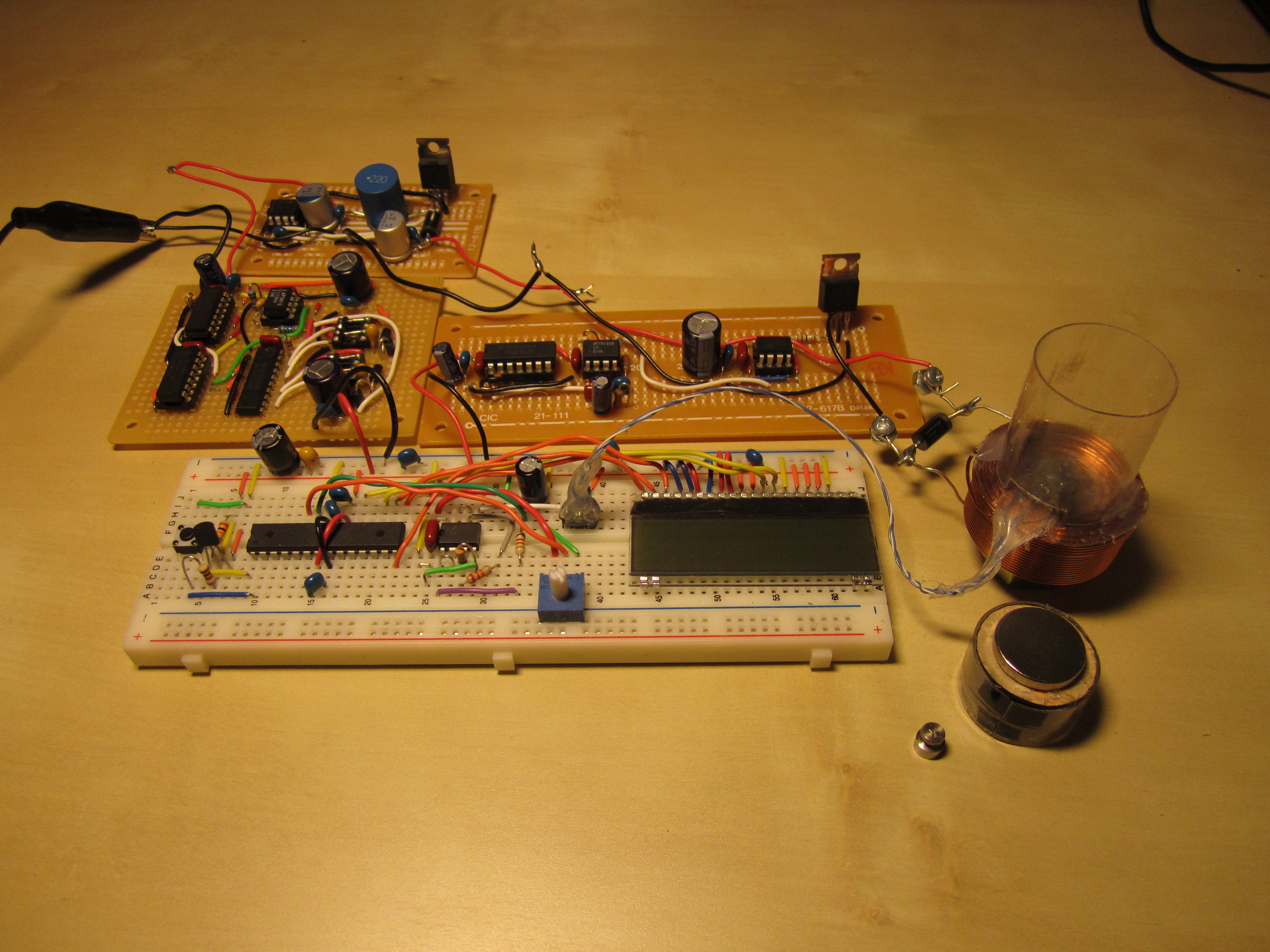
Small mass is 1g, the two bigger masses are 2g.
Pictures
 |
 |
 |
 |
 |
 |
I apologize for my camera skills & lighting.
Concept
 |
 |
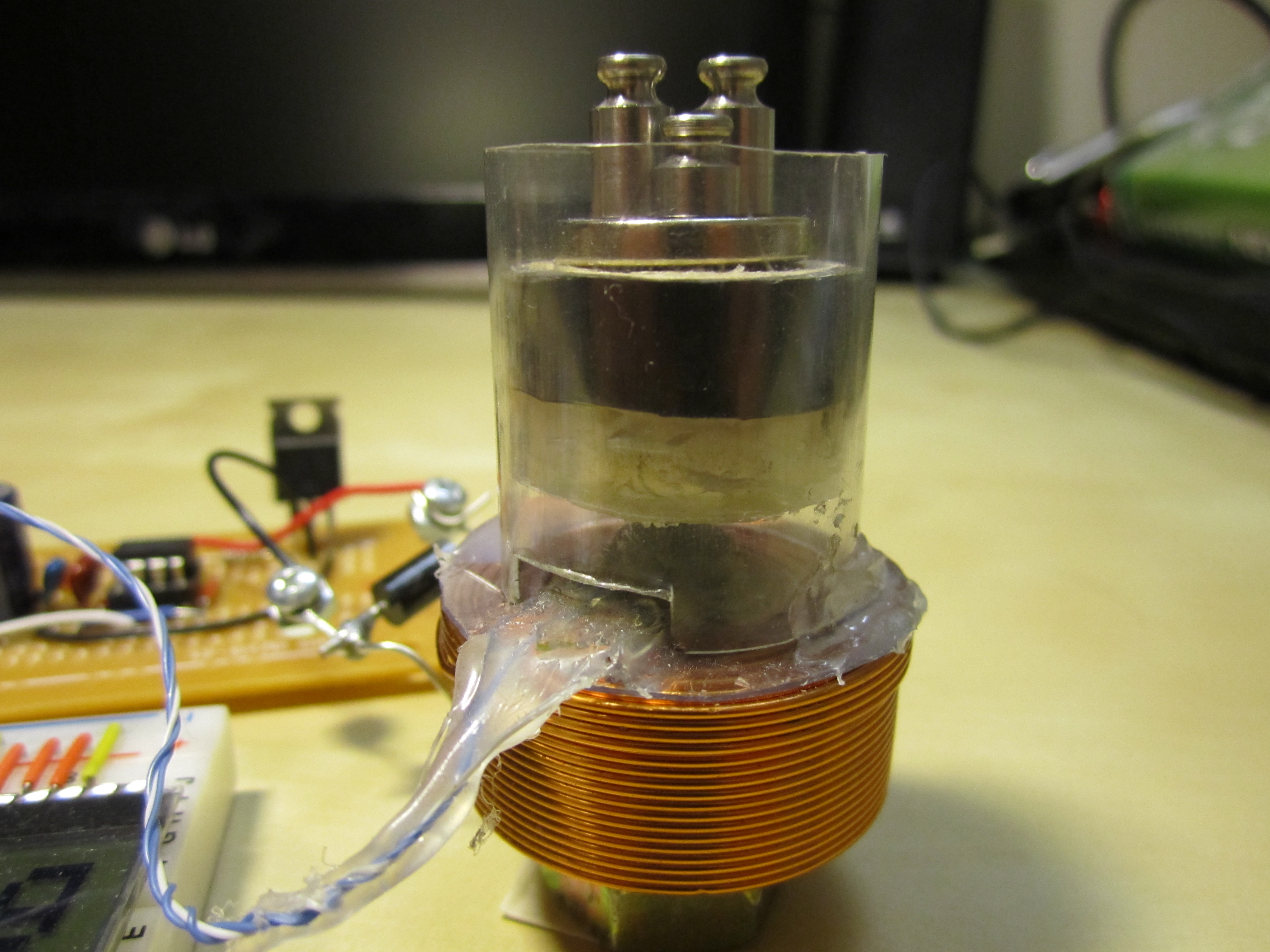
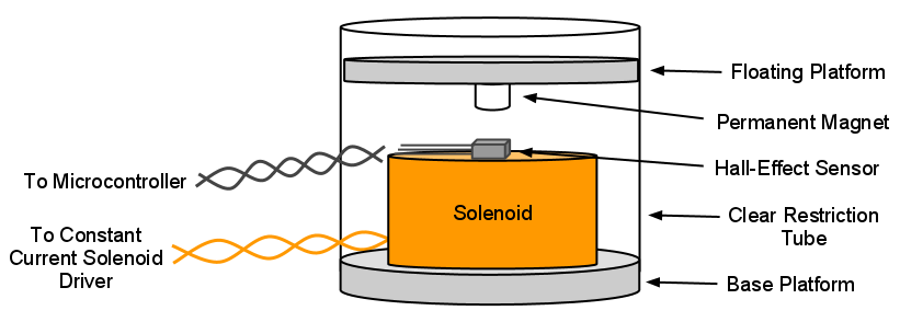
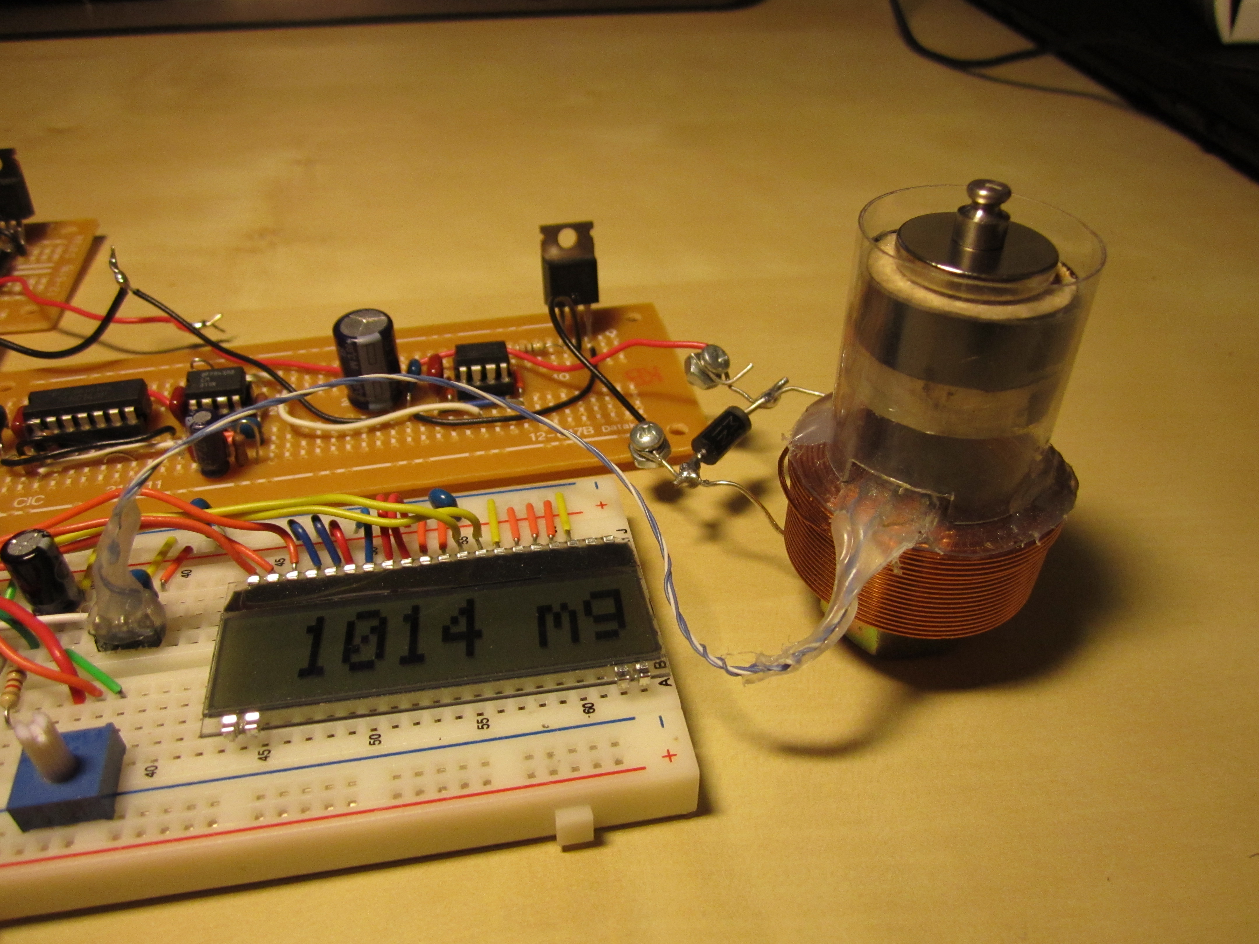
The battery-powered Levitating Digital Scale electromagnetically levitates a load platform, and uses a linear hall-effect sensor to measure the magnetic field strength to determine the weight of the platform. The levitating platform is embedded with a permanent magnet that opposes the magnetic field of a solenoid (the electromagnet). When a load is placed on the platform, the levitating platform will settle to a new height. Since the magnetic field created by the electromagnet is held constant, the linear hall-effect sensor experiences a stronger magnetic field due to the closer permanent magnet platform. Therefore, the reading on the linear hall-effect sensor increases, and can be correlated with the added weight on the scale.
The picture at the top shows a sketch of the physical system. The block diagram below the sketch shows the main blocks required to implement the system. The actual implementation (schematic) is shown and described below.
This levitating digital scale supports 0g - 20g masses, with a resolution of approximately 0.5g. To be conservative, the scale can most easily resolve to 1g.
Schematic
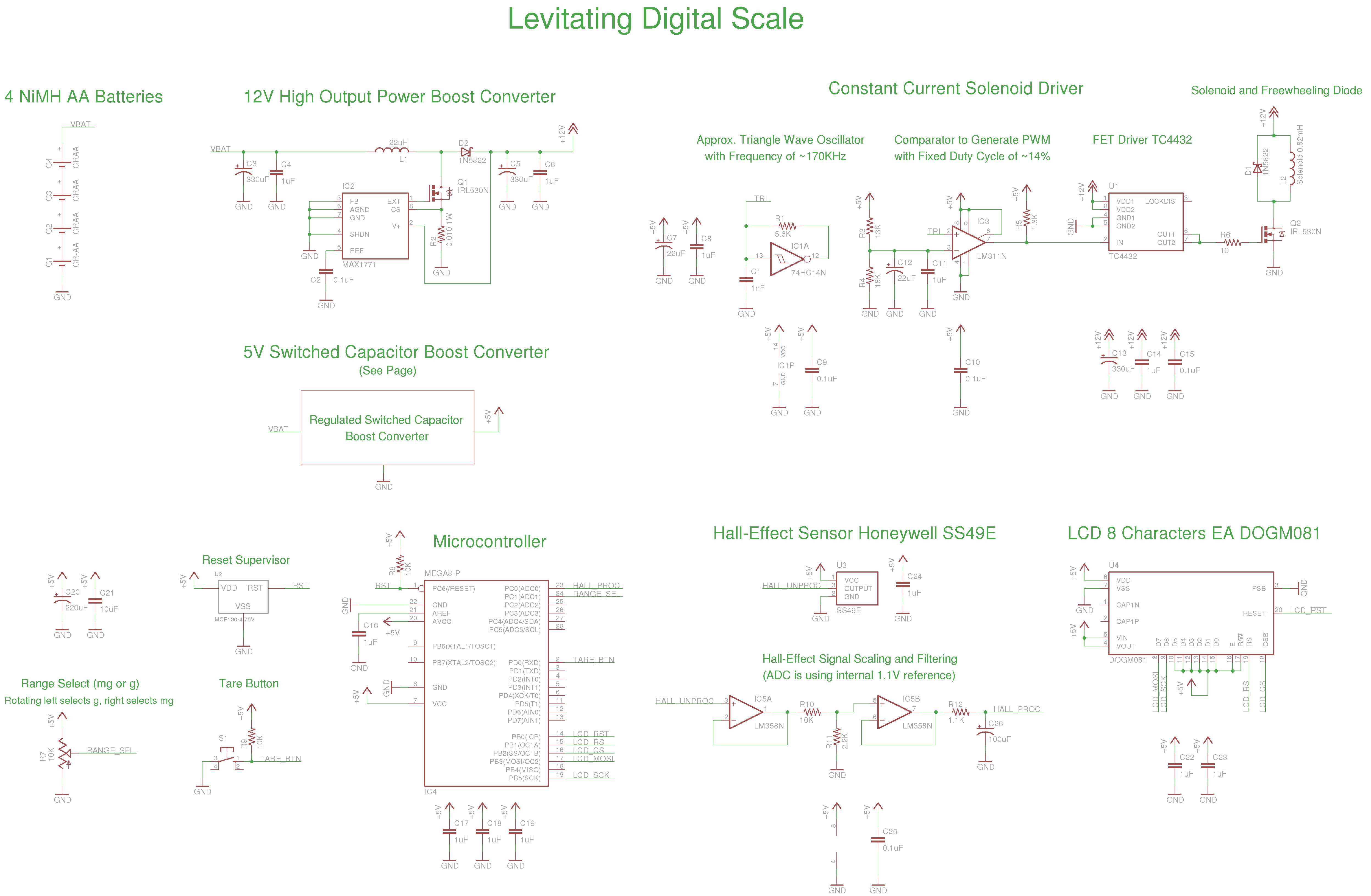 |
EAGLE schematic: lds.sch
High Output Power Boost Converter
In order to provide the necessary power in a usable form for the Constant Current Solenoid Driver, the input battery voltage is boosted to 12V with a boost converter controlled by the MAX1771. It drives an external FET (the IRL530N), accepts input voltages down to 2V, and is capable of delivering 24W of output power (with the external FET). The power requirements for the Constant Current Solenoid Driver is approximately 3.6W average, and I have found that this boost converter can provide this for an input voltage down to 3.0V.
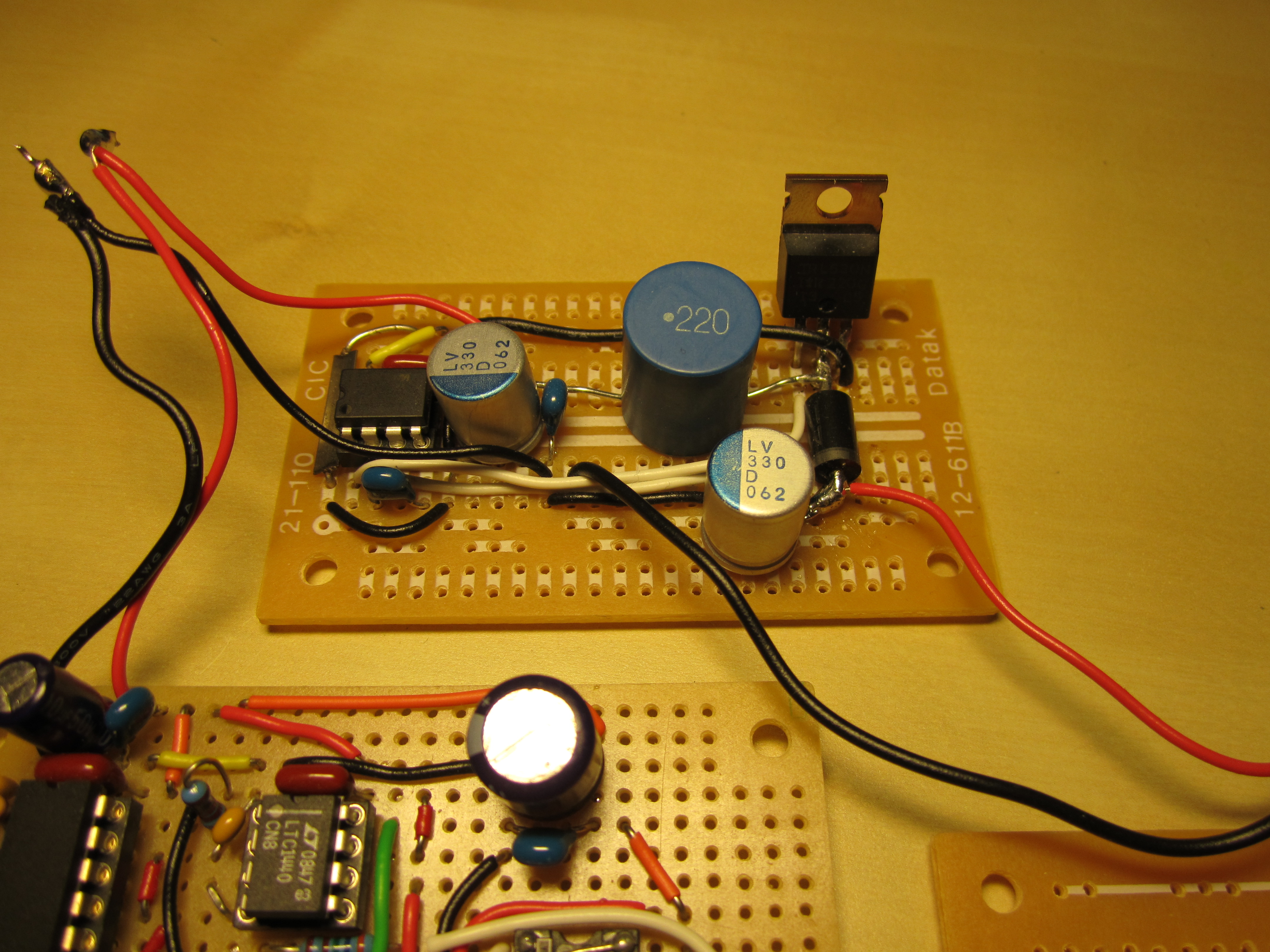
Switched Capacitor Boost Converter

The switched capacitor boost converter provides a regulated 5V rail for the microcontroller, Hall-Effect Sensor, and LCD. This was its own project that I decided to put to the test in the Levitating Digital Scale. See a complete description here: Discrete Switched Capacitor Boost Converter.
Constant Current Solenoid Driver
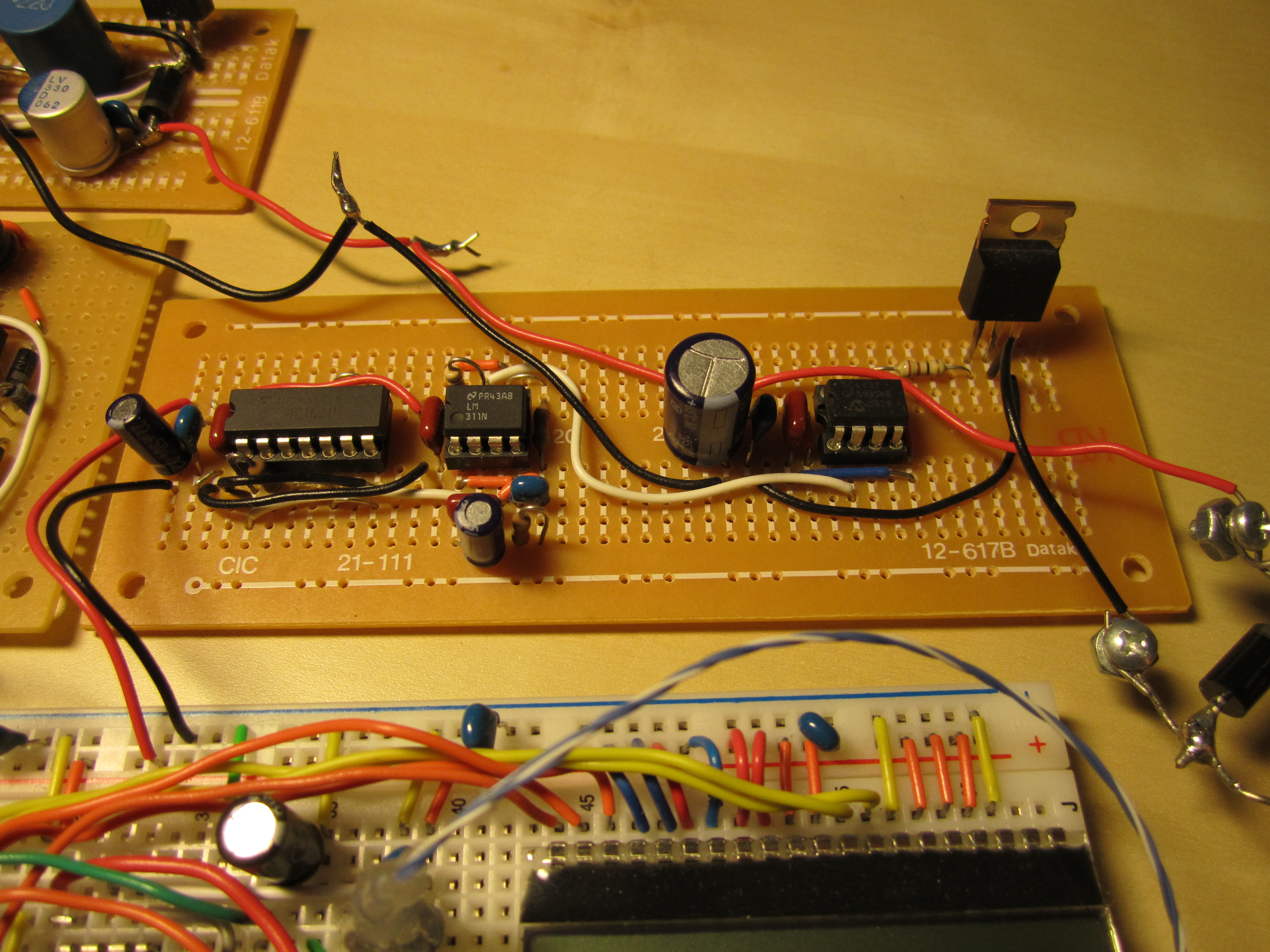
The constant current solenoid driver is essentially a PWM driven FET that pulls one terminal of the solenoid to ground, while the other is tied to +12V, therefore periodically ramping up current through the inductor. The freewheeling diode absorbs the back-EMF of the inductor when the FET is turned off (and helps keep some current flowing through the inductor). The PWM signal is generated by comparing the 170KHz approximately-triangle wave of a 74x14 based oscillator to a fixed voltage divider reference with the LM311. The fixed reference has been tuned so that the LM311 produces an approximately 14% duty cycle. This PWM logic signal is the input to the Microchip TC4432, a 1.5A MOSFET driver, which drives the pull-down FET.
For a very ball-park estimate: assuming that the 1N5822 has an on-resistance of approximately 0.2 ohms, and the solenoid’s internal resistance is 0.27 ohms, then the time constant L/R is 0.80mH / 0.5 ohms = 1.6 milliseconds. The 170KHz PWM signal has a period of 5.88 microseconds, so it’s safe to assume that the solenoid is in “continuous conduction mode” (a term usually used for magnetic DC/DC converters), meaning that it experiences a constant current with some minor ripple.
The duty cycle has been tuned for the maximum current draw that would not cause the 12V provided by the boost converter to droop significantly when the input voltage is at 3.0V. This duty cycle ensures that for 3.0V and up, the boost converter will be able to provide the necessary power for the constant current/levitation required in the solenoid.
Microcontroller, Hall-Effect Sensor, LCD
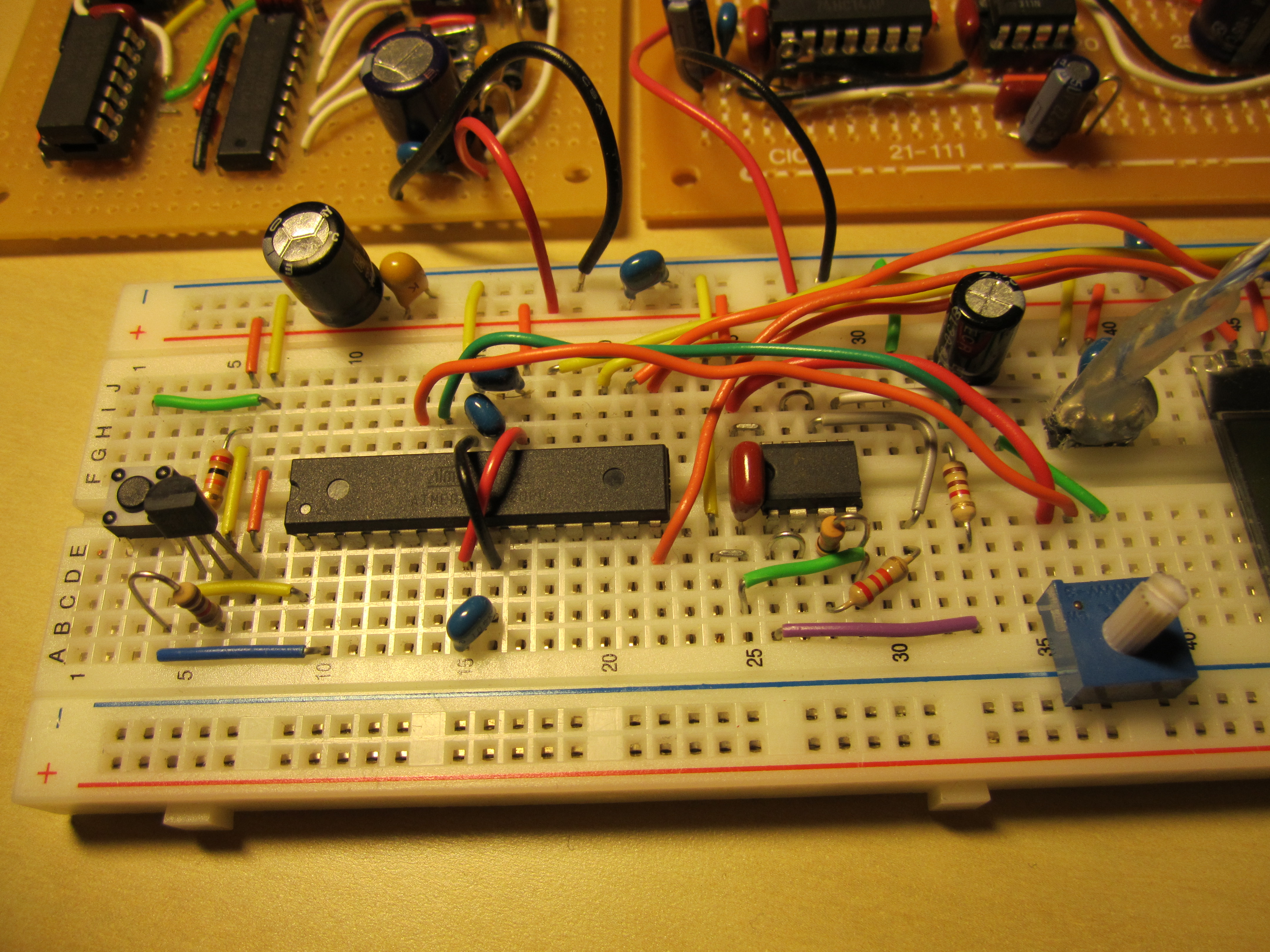
I used an Atmel ATMega168P for the microcontroller in this project. It has two user inputs: a “tare” button that zeros the scale, and an analog pot that is really just used as a switch between milligram and gram range selection (rotating it to the left puts the scale in gram mode, rotating it to the right puts the scale in milligram mode). A reset supervisor, the Microchip MCP130, is used to keep the microcontroller in reset while the 5V rail comes up during power-on (since this takes a non-trivial amount of time, roughly 2ms, and the microcontroller can begin to operate far below 5V while some of the other 5V parts cannot).
The linear hall-effect sensor is a Honeywell SS49E, which I purchased from Jameco. This sensor produces an analog voltage from 1.0V to 4.0V, proportional to the strength of the magnetic field (-1000 to +1000 Gauss) through one axis of the device. The sensitivity is 1.0-1.75 mV/G. The ADC on the microcontroller is operating using its internal 1.1V reference, so the hall-effect sensor’s output is first buffered, divided into the 1.1V range, and then passed through a single-pole low pass filter at 1.4Hz (I’m just interested in DC).
The 8-character LCD is the EA DOGM081-W, purchased from Mouser. These are pretty neat—even though they run $10.53 a piece: they are 0.1” pitch and breadboardable, offer a variety of interfaces (8-bit parallel, 4-bit parallel, SPI), operate at 3.3V/5V, and are very easy to talk to. I’m using it in the 5V SPI mode. The company also has 2-line and graphics LCD at similar prices, also available at Mouser.
Solenoid and Magnets
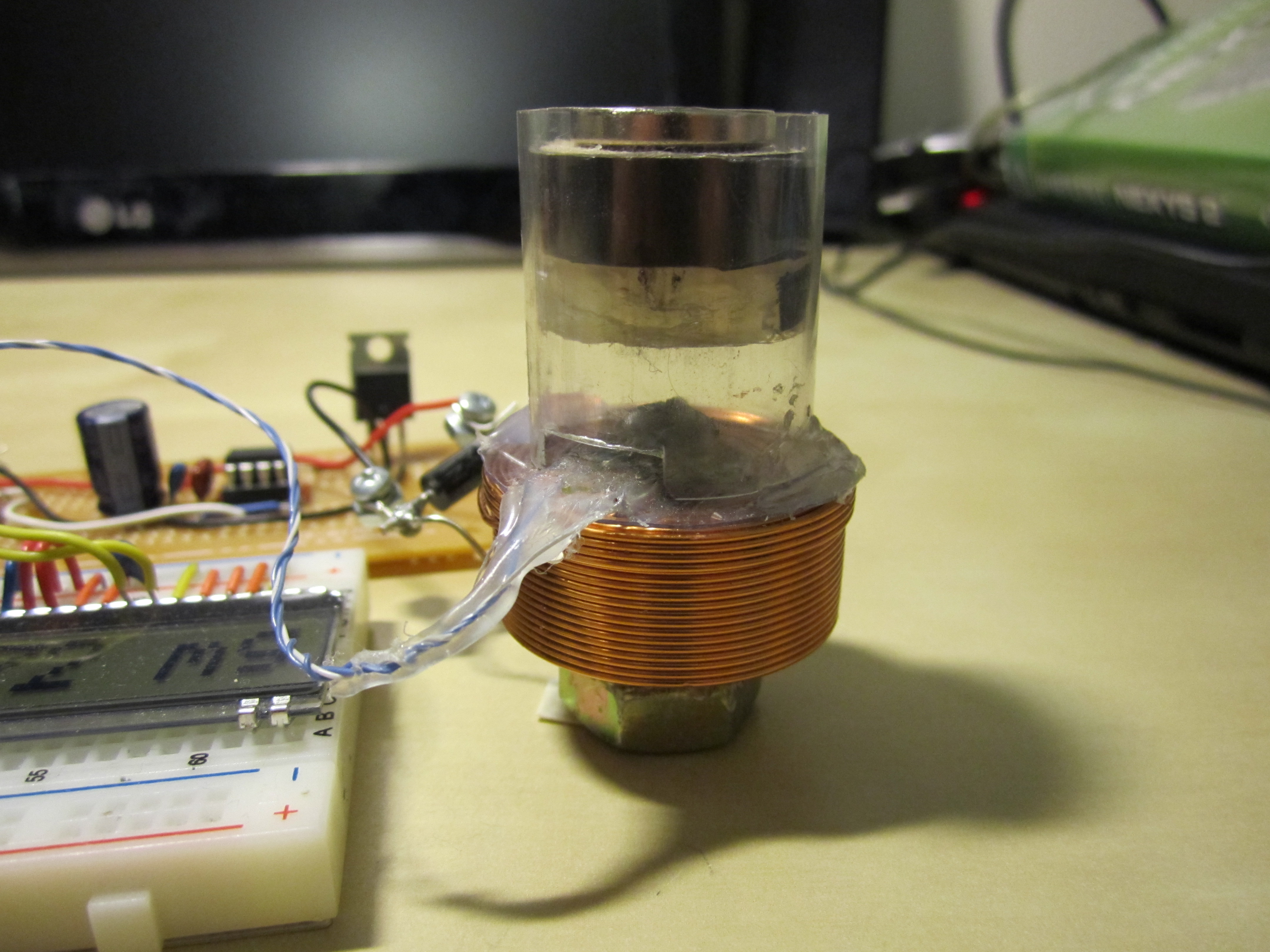
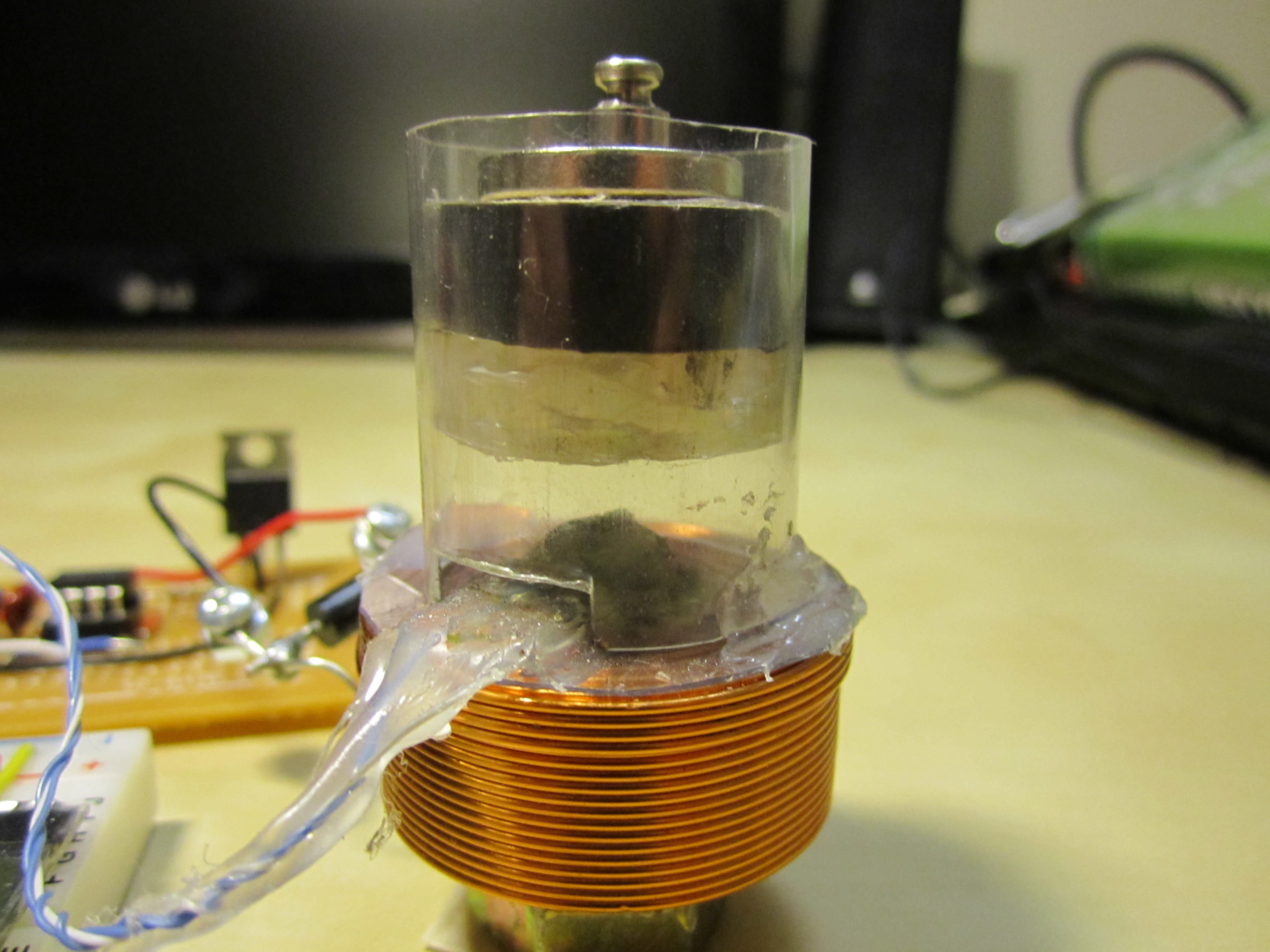
The solenoid is a 0.80mH Jantzen air core inductor, apparently they are usually used in cross-over networks in audio applications. I purchased it from Parts Express. I used a steel bolt inside the inductor as a core.
The levitating platform is made out of hot glue, a piece of cork, is wrapped in plastic, has one 1/4” by 1/4” rod neodymium magnet embedded inside, and one neodymium disc magnet on top of that platform that also serves as the loading surface.
The plastic used for the main tube and to wrap the platform was salvaged from the Magcraft neodymium magnet plastic casing.
Batteries
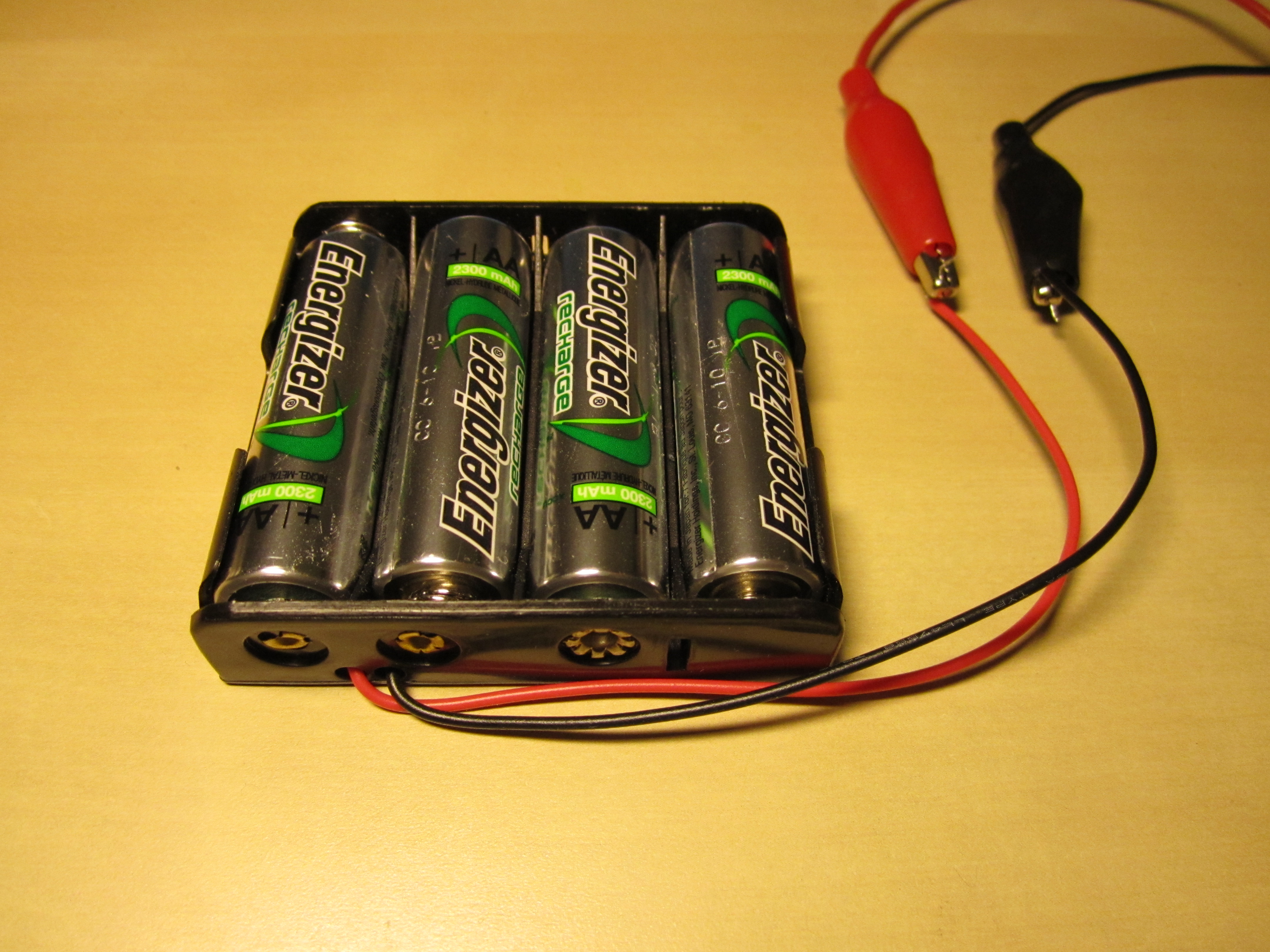
The Levitating Digital Scale is designed to operate from 4 AA NiMH batteries. I choose NiMH batteries for their current delivery capability, for being rechargeable, and their off the shelf availability. The nominal AA NiMH cell voltage is 1.2V, so 4xAA NiMH’s starts off at 4.8V. However, as expected, the total voltage makes a steady descent over time to down below 4V.
In terms of power, the electromagnetic levitation is expensive! so the battery life of this scale is limited to around 30 minutes. However, it can be run for longer periods of time from a typical AC/DC adapter.
Limitations
The Levitating Digital Scale has two main limitations.
First, the load must be carefully positioned so as not to alter the center of mass of the levitating platform. Otherwise, the platform will tilt and the calculated weight will be inaccurate (as the hall effect sensor is only seeing the z-component of the magnetic field, and the weight information will be in the other components if there is a tilt). Likewise, the solenoid base must be mounted firmly and evenly on a surface to ensure that the solenoid and sensor itself isn’t at a tilt relative to the platform.
Second, the inductor I chose for the solenoid isn’t rated for the current being driven through it, so for long periods of use (> 5 minutes), it will heat up. I believe a consequence of this is that the internal resistance of the inductor increases, meaning that less of the energy delivered to the inductor is being stored in the magnetic field, and more is lost to heat. This causes the levitation height to fall slightly (a few mm) over time (and the scale will report a greater weight). So, the scale needs to be periodically re-tared.
I consider these two limitations to be the primary roadblocks in exceeding 0.5g resolution. As some experts have pointed out, for better resolution and precision there are other mechanical issues such as friction, and temperature stability that should be addressed. For a battery-powered electromagnetic digital scale, I was pretty happy with reaching 0.5g.
Data and Weight
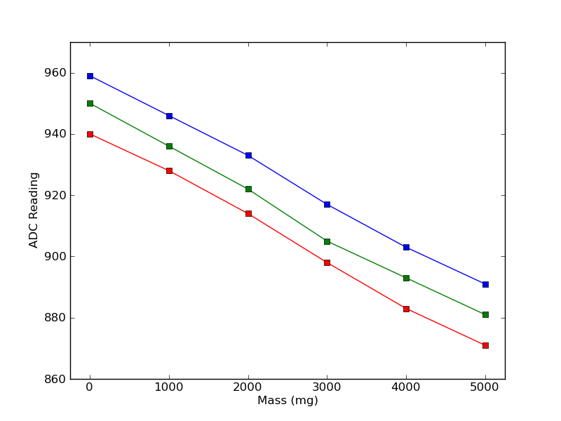
I bought an inexpensive calibration mass set and recorded ADC readings of the hall-effect sensor (I printed them out on the LCD) with 1g intervals to get a better sense of the relationship between magnetic field strength and load weight. I assumed early on that the system would be terribly nonlinear, since the upwards magnetic field strength from the solenoid falls of at 1/r^2 approximately (assuming an ideal solenoid), and the if you pretend the platform is something like a dipole, then its field strength falls off at 1/r^3. In short, I was expecting a weird but monotonic curve.
To my surprise, I observed this instead:
 |
import pylab

y1 = [940, 928, 914, 898, 883, 871]
y2 = [950, 936, 922, 905, 893, 881]
y3 = [959, 946, 933, 917, 903, 891]
x = [0, 1000, 2000, 3000, 4000, 5000]

pylab.xlabel("Mass (mg)")
pylab.ylabel("ADC Reading")

pylab.plot(x, y1, 'rs-')
pylab.plot(x, y2, 'gs-')
pylab.plot(x, y3, 'bs-')
pylab.xlim(xmin = -250, xmax = 5250)
pylab.ylim(ymin = 860, ymax = 970)
pylab.savefig('lds_initial_data.png')
pylab.show()
The relationship seemed very much linear. The three series in the graph show the data collected as the scale had been operating for successively longer periods of time, i.e. the solenoid was probably pretty warm for the data collected in the red series. Some of the variation between the data points can be attributed to me not completely understanding the center of mass limitation I described in the previous section at the time (so I may have not put the calibration weight on the right place on the platform).
I averaged the slopes between the data points for all three series and settled on a slope of 13.8 per 1000mg (which you can see be used in the code below). Since I’m assuming the relationship is linear, it makes it very easy to implement “tare” functionality. In the code below, to implement tare I take 5 consecutive readings seperated by 500ms, average them, and use the result as an offset that I subtract from future readings before using the relationship 1000 mg/13.8 to calculate the weight.
Of course the scale isn’t really linear, but the approximation serves well for rounded 0.5g resolution (I also tested the scale with 0.5g and 0.2g calibration masses). With heavier objects (>10g), the approximation becomes less accurate.
With some more analysis and a more robust mechanical system, I think the scale could definitely meet and surpass 0.1g resolution.
Additional Pictures
 |
 |
Code
#include <avr/io.h>
#include <avr/interrupt.h>
#include <avr/pgmspace.h>
#include <util/delay.h>
#include <stdint.h>
//#include "table.h"

void delay_ms(uint16_t duration) {
    for (; duration > 0; duration--)
        _delay_ms(1);
}

///////////////////////////////////////////////////////////////////////////////

void adc_init(void) {
    /* Configure ADC Multiplexer
     * [7:6] REFS1:0 = 11 for Internal 1.1V Reference
     * [3:0] MUX3:0 = 0000 for ADC0, 0001 for ADC1 */
    ADMUX = (1<<7)|(1<<6);

    /* Configure Digital Input Disable Register 0
     * [5:0] = ADC5D - ADC0D = 11111 to disable digital input buffer
     *         for ADC0-ADC5 to reduce power consumption. */
    DIDR0 = 0x1F;

    /* Configure ADC Control and Status Register B
     * [2:0] ADTS2:0 = 000 for Free Running Mode */
    ADCSRB = 0x00;

    /* Configure ADC Control and Status Register A
     * [7] ADEN = 1 to enable ADC
     * [2:0] ADPS2:0 = 111 for 128 prescaling = 156.25kHz */
    ADCSRA = ((1<<7) | (1<<2) | (1<<1) | (1<<0));
}

uint16_t adc0_poll(void) {
    uint16_t data;

    /* Select our channel */
    ADMUX &= 0xF0;
    ADMUX |= (0 & 0x0F);

    /* Start the conversion */
    ADCSRA |= (1<<6);

    /* Wait for the conversion to complete */
    /* (wait for the ADIF flag to be set) */
    while ( (ADCSRA & (1<<6)) )
        ;

    data = ADCL;
    data |= (ADCH << 8);
    return data;
}

uint16_t adc1_poll(void) {
    uint16_t data;

    /* Select our channel */
    ADMUX &= 0xF0;
    ADMUX |= (1 & 0x0F);

    /* Start the conversion */
    ADCSRA |= (1<<6);

    /* Wait for the conversion to complete */
    /* (wait for the ADIF flag to be set) */
    while ( (ADCSRA & (1<<6)) )
        ;

    data = ADCL;
    data |= (ADCH << 8);
    return data;
}

///////////////////////////////////////////////////////////////////////////////

#define LCD_SPI_Set_Data()    (PORTB |= (1<<1))
#define LCD_SPI_Set_Command()    (PORTB &= ~(1<<1))
#define LCD_SPI_CS_Low()    (PORTB &= ~(1<<2))
#define LCD_SPI_CS_High()    (PORTB |= (1<<2))

void lcd_spi_init(void) {
    /* Set SCK, MOSI, CS, RS, Reset to outputs */
    DDRB = (1<<5)|(1<<3)|(1<<2)|(1<<1)|(1<<0);
    /* Set SPICR to Enable, Master, Fck/16
     * MSB first, CPOL=0, CPHA=0. */
    SPCR = (1<<SPE)|(1<<MSTR)|(1<<SPR0);
    /* Bring CS High */
    LCD_SPI_CS_High();
}

void lcd_spi_command(uint8_t command) {
    LCD_SPI_Set_Command();
    _delay_us(10);

    LCD_SPI_CS_Low();
    SPDR = command;
    while (!(SPSR & (1<<SPIF)))
        ;
    LCD_SPI_CS_High();
}

void lcd_spi_data(uint8_t data) {
    LCD_SPI_Set_Data();
    _delay_us(10);

    LCD_SPI_CS_Low();
    SPDR = data;
    while (!(SPSR & (1<<SPIF)))
        ;
    LCD_SPI_CS_High();
}

void lcd_init(void) {
    lcd_spi_init();
    /* Reset the LCD */
    PORTB &= ~(1<<0);
    delay_ms(200);
    PORTB |= (1<<0);
    delay_ms(10);

    /* Send initialization sequence */
    lcd_spi_command(0x31);
    _delay_us(50);
    lcd_spi_command(0x1c);
    _delay_us(50);
    lcd_spi_command(0x51);
    _delay_us(50);
    lcd_spi_command(0x6a);
    _delay_us(50);
    lcd_spi_command(0x74);
    _delay_us(50);
    lcd_spi_command(0x30);
    _delay_us(50);
    lcd_spi_command(0x0c);
    _delay_us(50);
    lcd_spi_command(0x01);
    _delay_ms(5);
    lcd_spi_command(0x06);
    _delay_us(50);
}

void lcd_print(char message[8]) {
    uint8_t i;

    /* Clear display */
    lcd_spi_command(0x01);
    _delay_ms(2);
    /* Print the 8 characters */
    for (i = 0; i < 8; i++) {
        lcd_spi_data(message[i]);
        _delay_ms(2);
    }
}

///////////////////////////////////////////////////////////////////////////////

void lcd_print_weight_mg(int16_t weight) {
    char message[8] = "        ";
    char maxMsg[8] = "  MAX mg";
    char zeroMsg[8] = {' ', ' ', ' ', 0xF9, '0', ' ', 'm', 'g'};
    uint8_t i;

    if (weight == -1) {
        lcd_print(maxMsg);
        return;
    } else if (weight == -2 || weight < -2) {
        lcd_print(zeroMsg);
        return;
    }

    for (i = 0; i < 5; i++) {
        message[4-i] = (weight % 10) + '0';
        weight /= 10;
        if (weight == 0)
            break;
    }
    message[5] = ' ';
    message[6] = 'm';
    message[7] = 'g';
    lcd_print(message);
}

void lcd_print_weight_g(int16_t weight) {
    char message[8] = "        ";
    char maxMsg[8] = "   MAX g";
    char zeroMsg[8] = {' ', ' ', ' ', ' ', 0xF9, '0', ' ', 'g'};
    uint8_t i;

    uint16_t roundedWeight;

    if (weight == -1) {
        lcd_print(maxMsg);
        return;
    } else if (weight == -2 || weight < -2) {
        lcd_print(zeroMsg);
        return;
    }

    roundedWeight = weight / 1000;
    /* Round up if necessary */
    if ((weight - (roundedWeight*1000)) >= ((((roundedWeight+1)*1000) - (roundedWeight*1000)) / 2))
        roundedWeight++;

    for (i = 0; i < 6; i++) {
        message[5-i] = (roundedWeight % 10) + '0';
        roundedWeight /= 10;
        if (roundedWeight == 0)
            break;
    }
    message[6] = ' ';
    message[7] = 'g';
    lcd_print(message);
}

uint16_t tare_scale(void) {
    uint16_t offset;

    lcd_print("Calib...");
    offset = adc0_poll();
    delay_ms(500);
    offset += adc0_poll();
    delay_ms(500);
    offset += adc0_poll();
    delay_ms(500);
    offset += adc0_poll();
    delay_ms(500);
    offset += adc0_poll();
    offset /= 5;

    lcd_print_weight_mg(offset);
    delay_ms(1000);
    return offset;
}

int main(void) {
    uint16_t mode;
    uint16_t zeroOffset;
    uint32_t sample;
    char debounce;

    /* Tare button as input */
    DDRD = ~((1<<0));

    /* Some start up time for other parts to settle */
    delay_ms(200);

    /* Initialize the ADC */
    adc_init();

    lcd_init();
    lcd_print("LDS V1.0");
    delay_ms(2000);

    zeroOffset = tare_scale();

    while (1) {
        delay_ms(450);

        /* Check tare scale button */
        if (!(PIND & (1<<0))) debounce = 1;
        else debounce = 0;

        delay_ms(100);

        /* Tare the scale if the tare scale button has been pressed */
        if (debounce && !(PIND & (1<<0)))
            zeroOffset = tare_scale();

        /* Check mode pot */
        mode = adc1_poll();
        mode = (mode > 512);
        sample = adc0_poll();

        /* The hall-effect axis is oriented such that the voltage
                 * it outputs decreases as the permanent magnet platform is
                 * closer */

        /* If the reading is more than the zero offset, it weighs less
         * than zero */
        if (sample > zeroOffset) {
            if (mode) lcd_print_weight_mg(-2);
            else lcd_print_weight_g(-2);
            continue;
        /* A reading below 100 is considered the MAX of the scale */
        } else if (sample < 100) {
            if (mode) lcd_print_weight_mg(-1);
            else lcd_print_weight_g(-1);
            continue;
        }

        /* Calculate and print the weight */

        sample = zeroOffset - sample;
        /* Linear at 13.8 per 1000 mg */
        sample *= 10000;
        sample /= 138;
        if (mode) lcd_print_weight_mg(sample);
        else lcd_print_weight_g(sample);
    }

    return 0;
}
Comments
Feel free to leave comments, corrections, critique.
