PA0RDT Mini-Whip Build
This HF active antenna is a build of the PA0RDT Mini-Whip from a kit I bought on eBay. It covers the entire HF band (3 to 30 MHz) and below (supposedly down to 10 kHz). It’s powered by an external 12-15V supply, consuming about 50 mA.
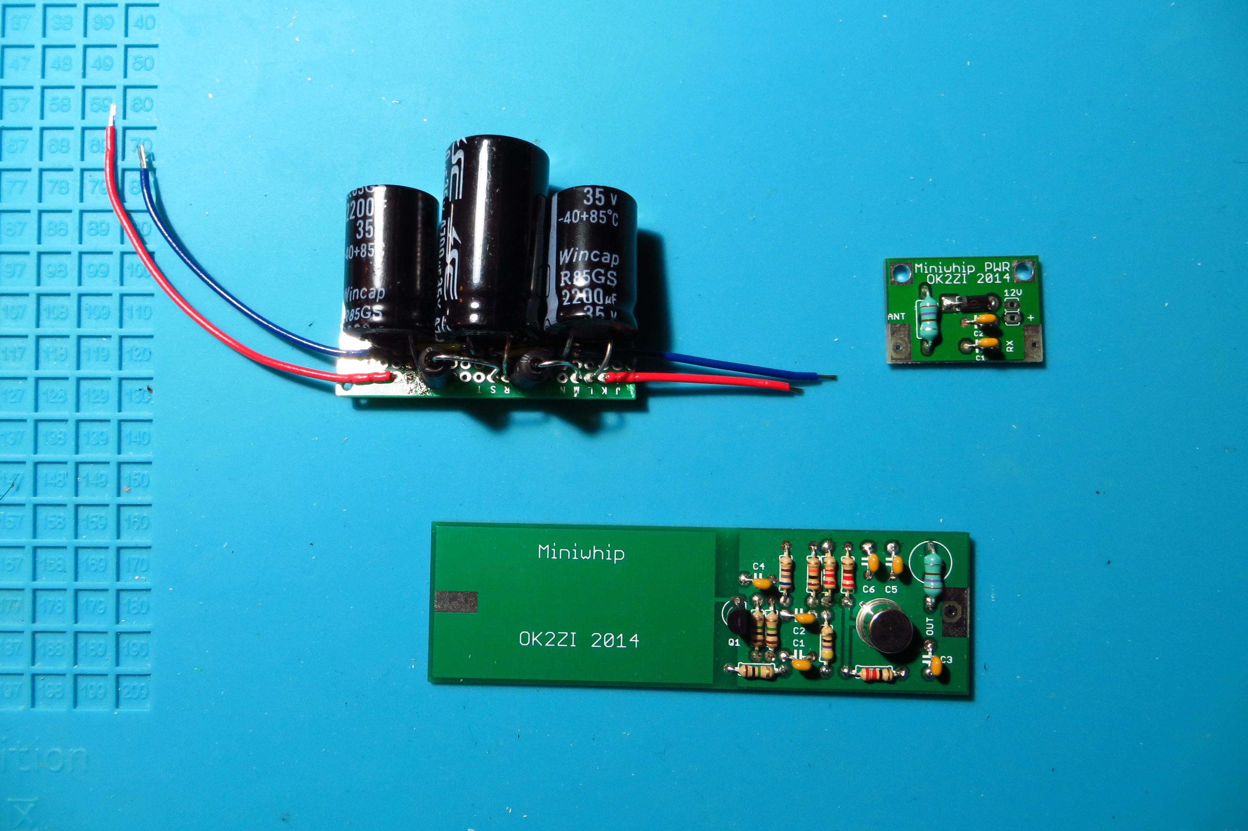 |
The kit consists of the antenna and a DC bias tee, shown assembled at the bottom and top right, respectively. I opted to power the antenna from a bench power supply, rather than a battery, so I also built a two stage LC power supply filter on a prototype board, shown assembled at the top left.
 |
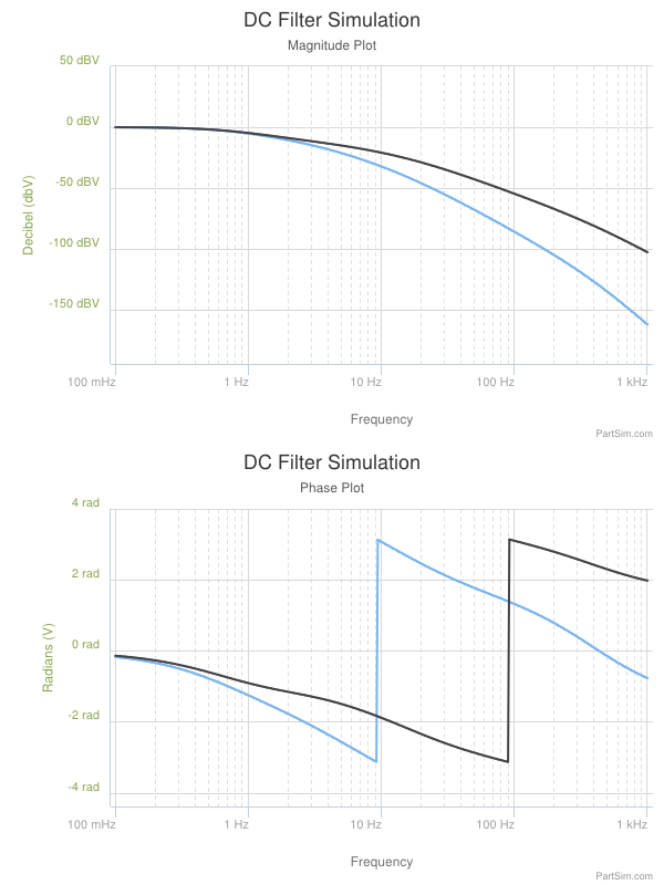 |
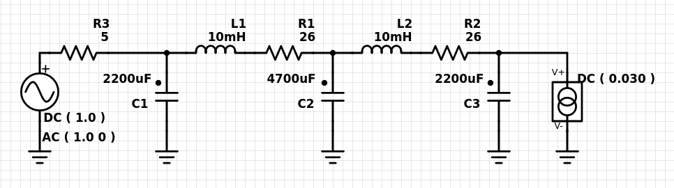
I used SPICE on PartSim to model the DC power supply filter and pick suitable component values. The schematic and frequency response are shown above. The frequency response is -91 dBV at 120 Hz.
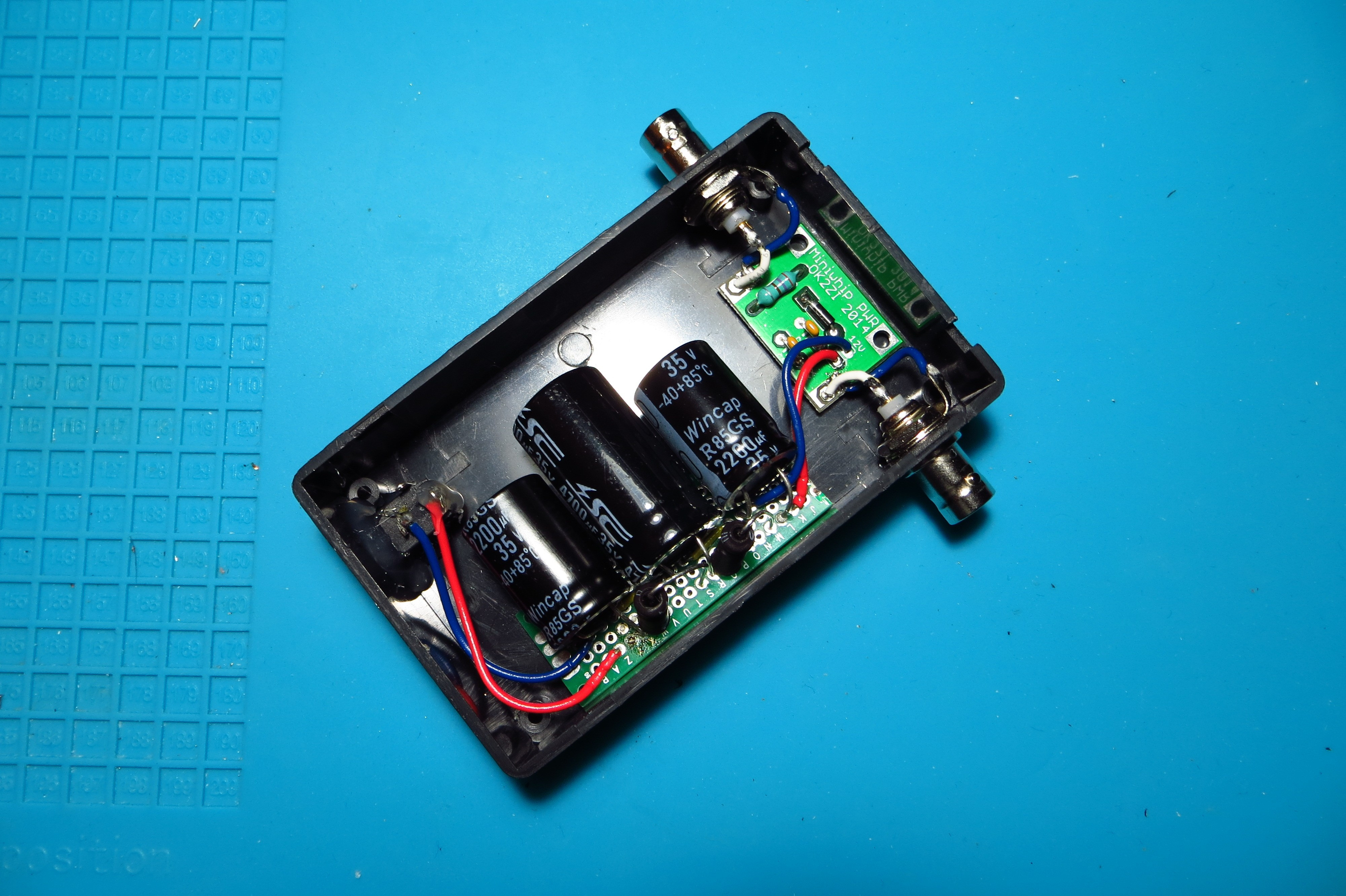 |
I mounted the power supply filter and DC bias tee in a plastic container, exposing the bias tee connections with BNC jacks and the power supply filter input with a power barrel jack.
 |
I enclosed the antenna in a PVC pipe with two end caps. The top end cap has a bolted metal hook for hanging, and the bottom end cap has a BNC jack for the antenna’s RF output and DC power input.
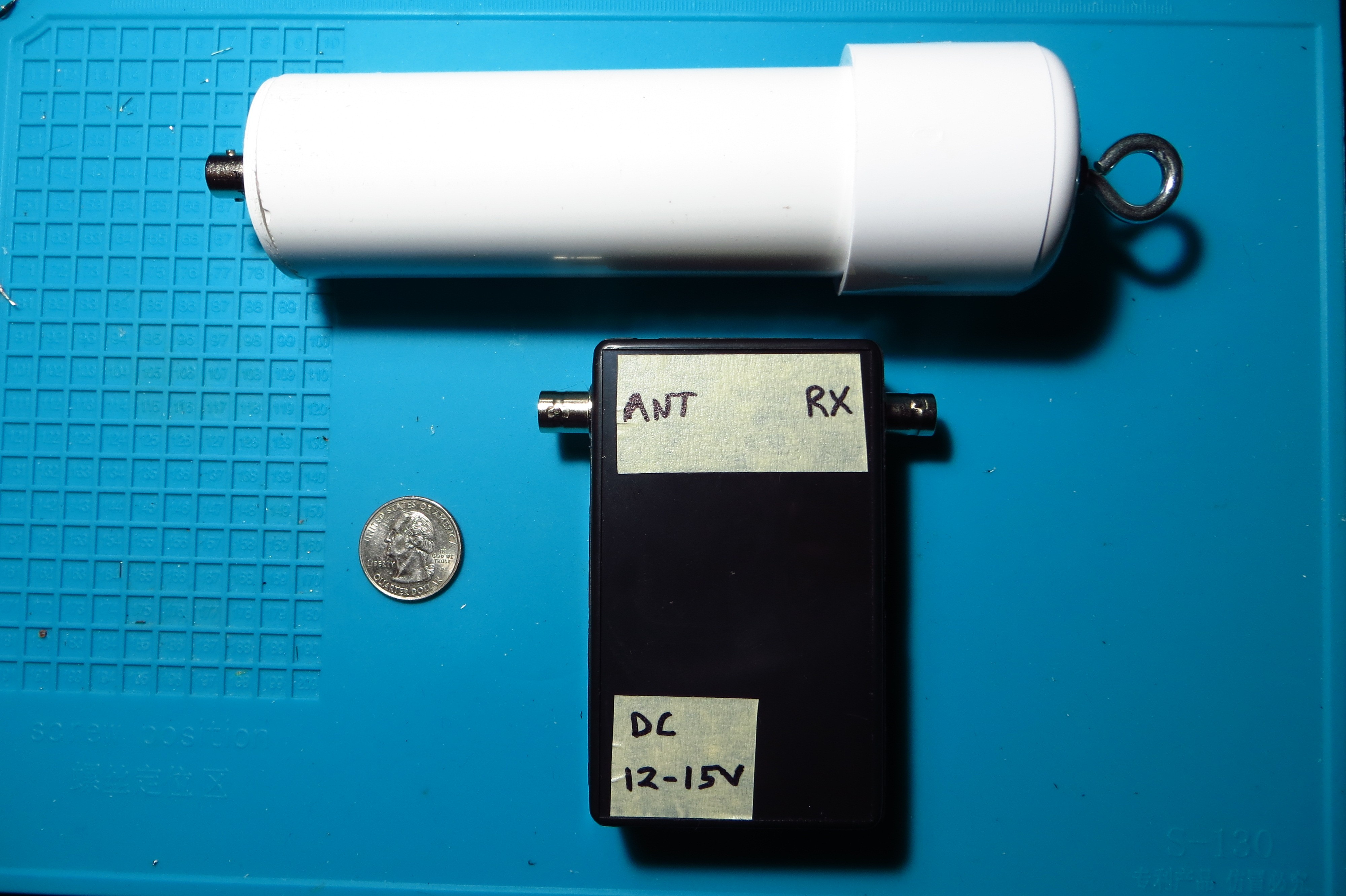 |
The fully assembled antenna and power supply filter / bias tee box are shown above.
Overall, the active antenna works surprisingly well, given its size. I tested it receiving WWV, while sweeping the power supply voltage from 8 to 15 V, and noticed the signal quality improve with increasing supply voltage – up to a point.
However, I noticed slightly more voltage drop across my power supply filter than I had predicted when I tested it with a resistive load. The series resistance of the inductors I chose turned out to be worse than I had modeled. This could be improved with better components.
