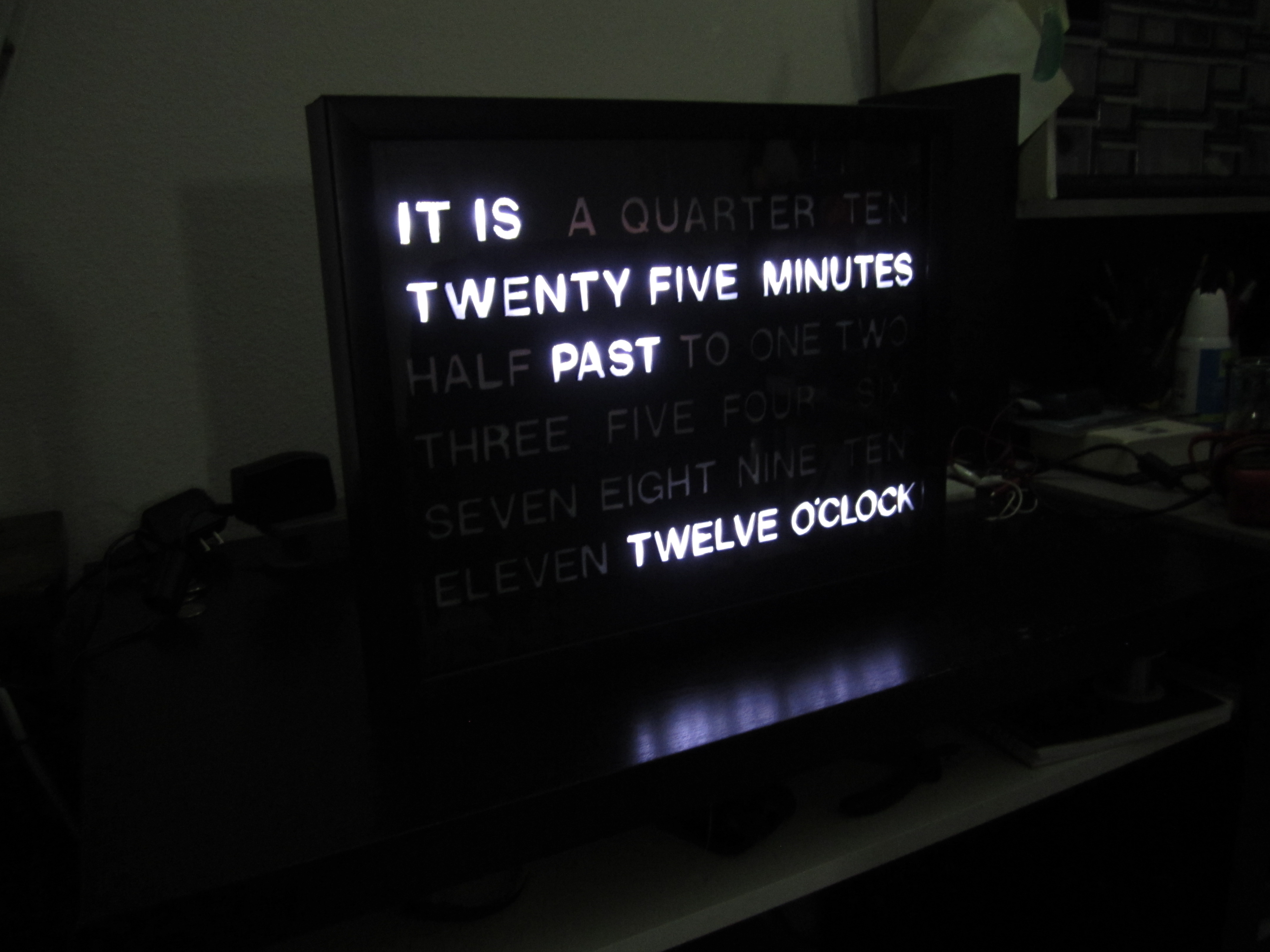
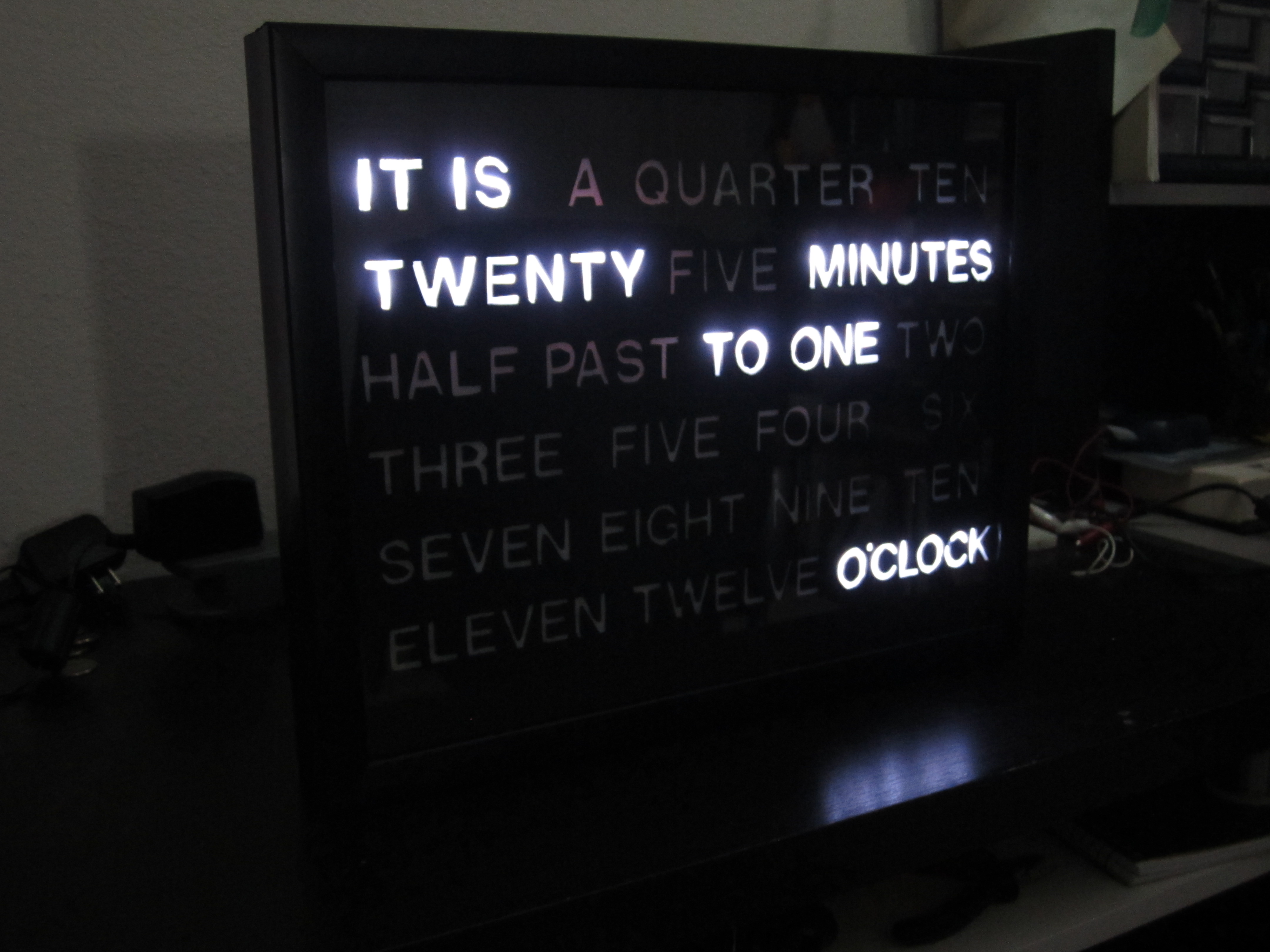
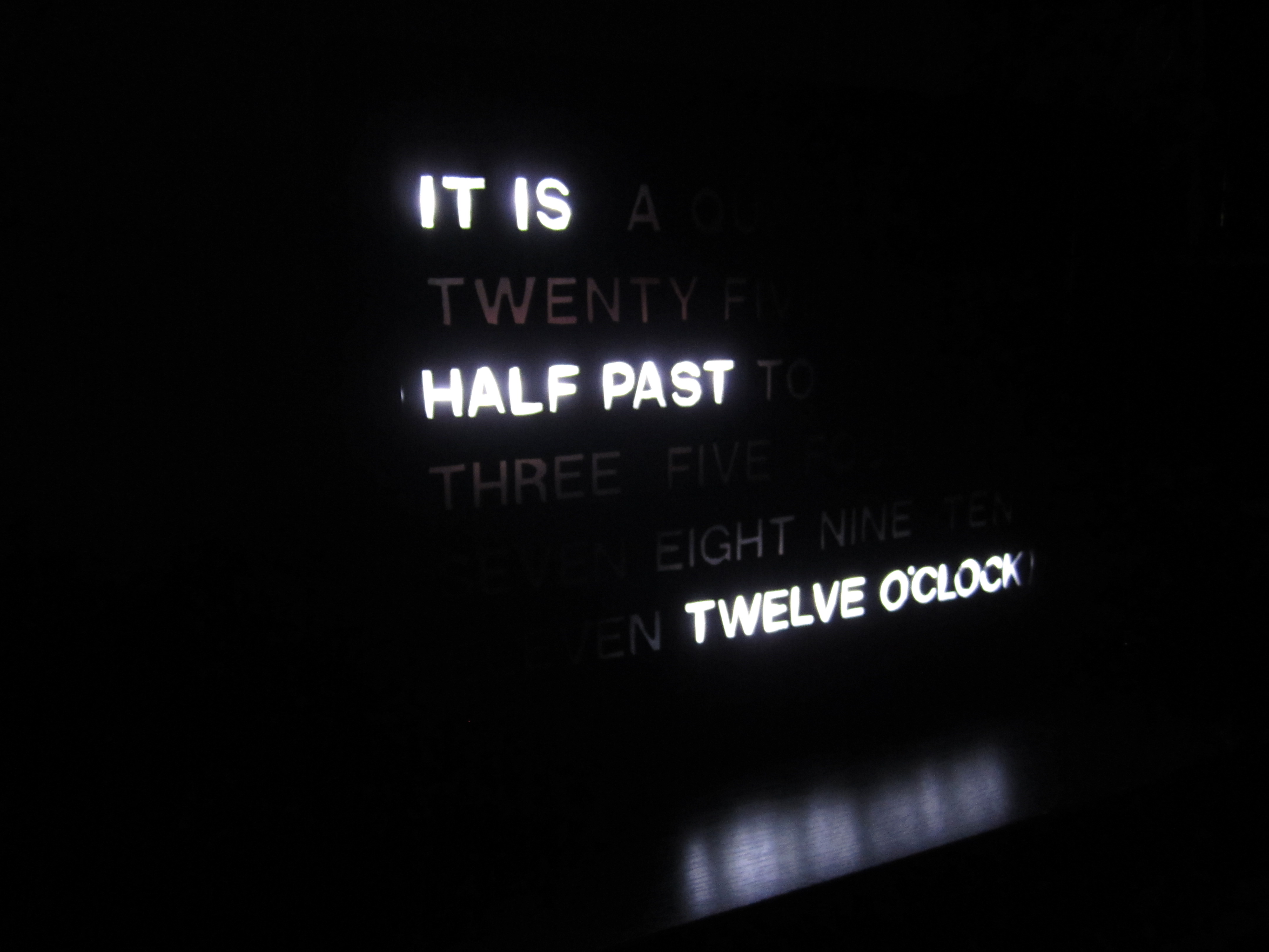
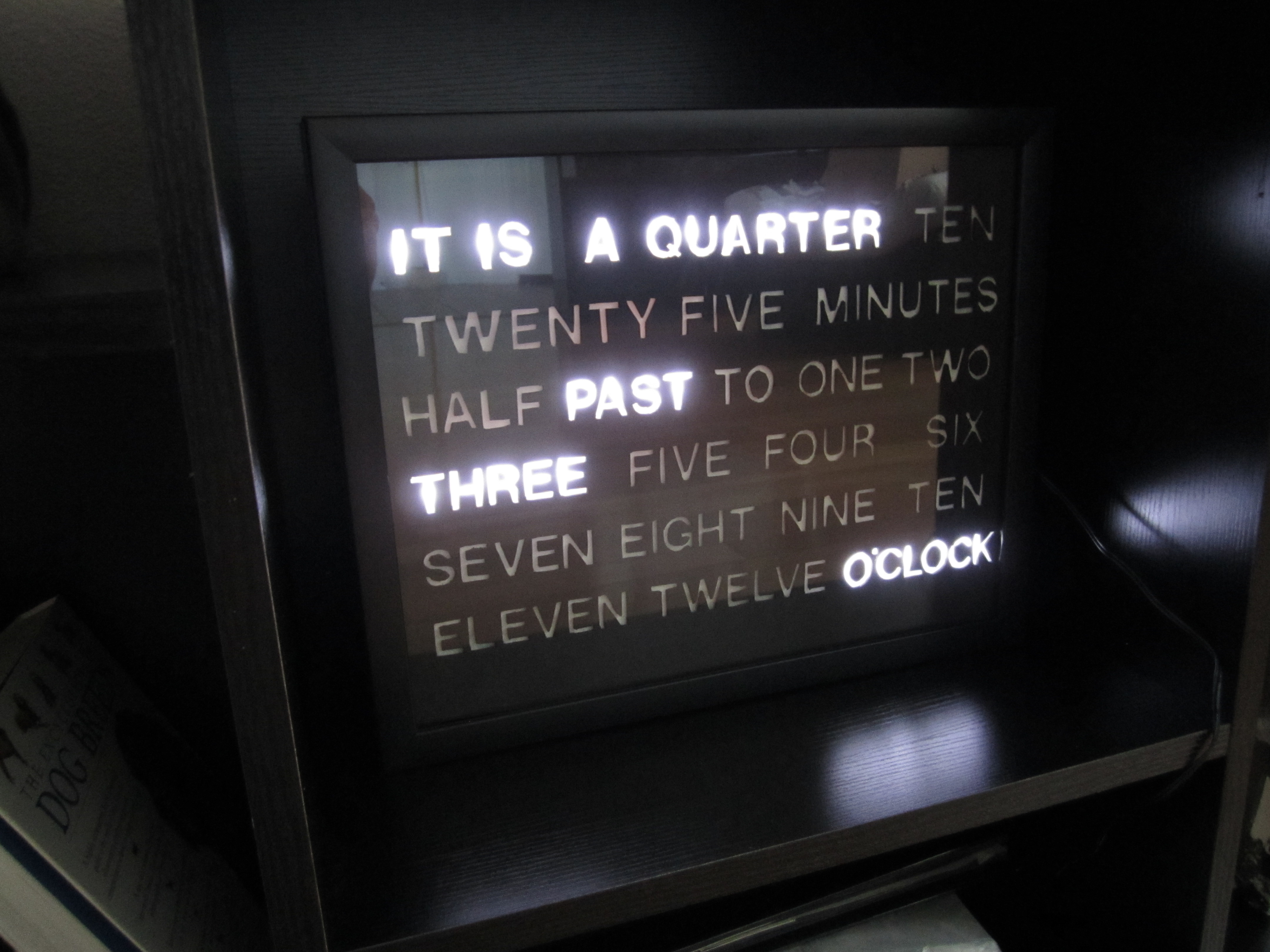
Word Clock
Pictures
 |
 |
 |
 |
 |
 |
 |
 |
 |
 |
 |
 |
 |
 |
Video
Videos of some pattern tests of the word clock:
Source
GitHub: https://github.com/vsergeev/wclock
Description
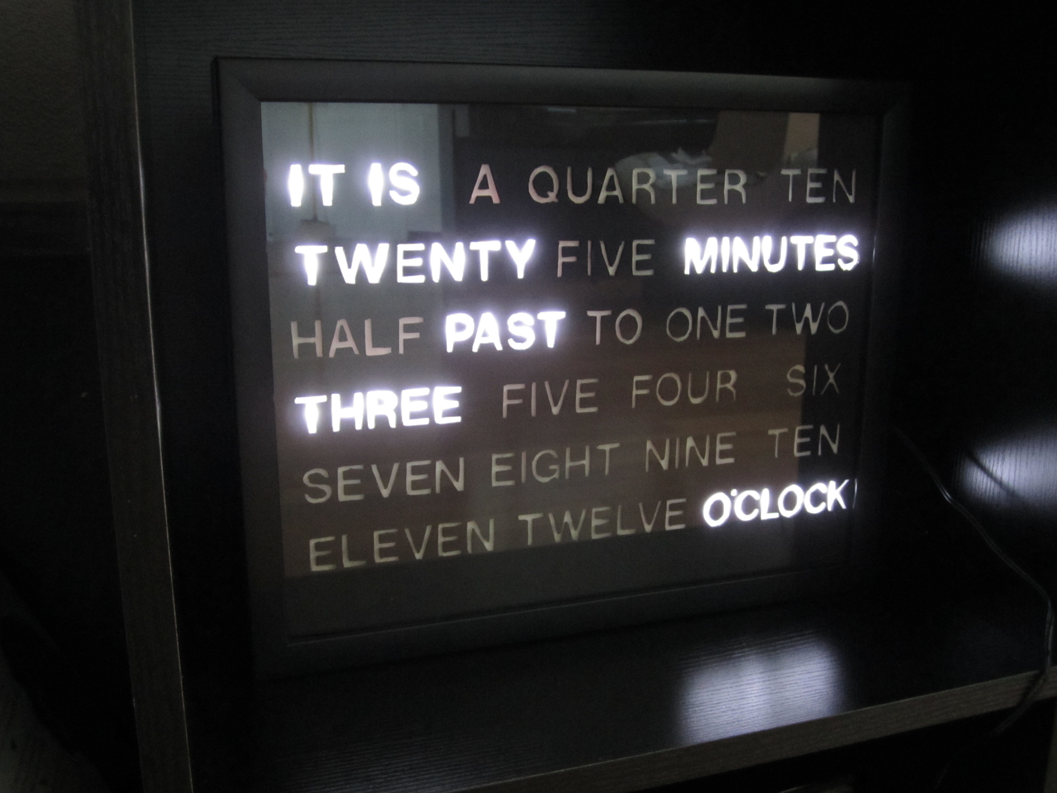
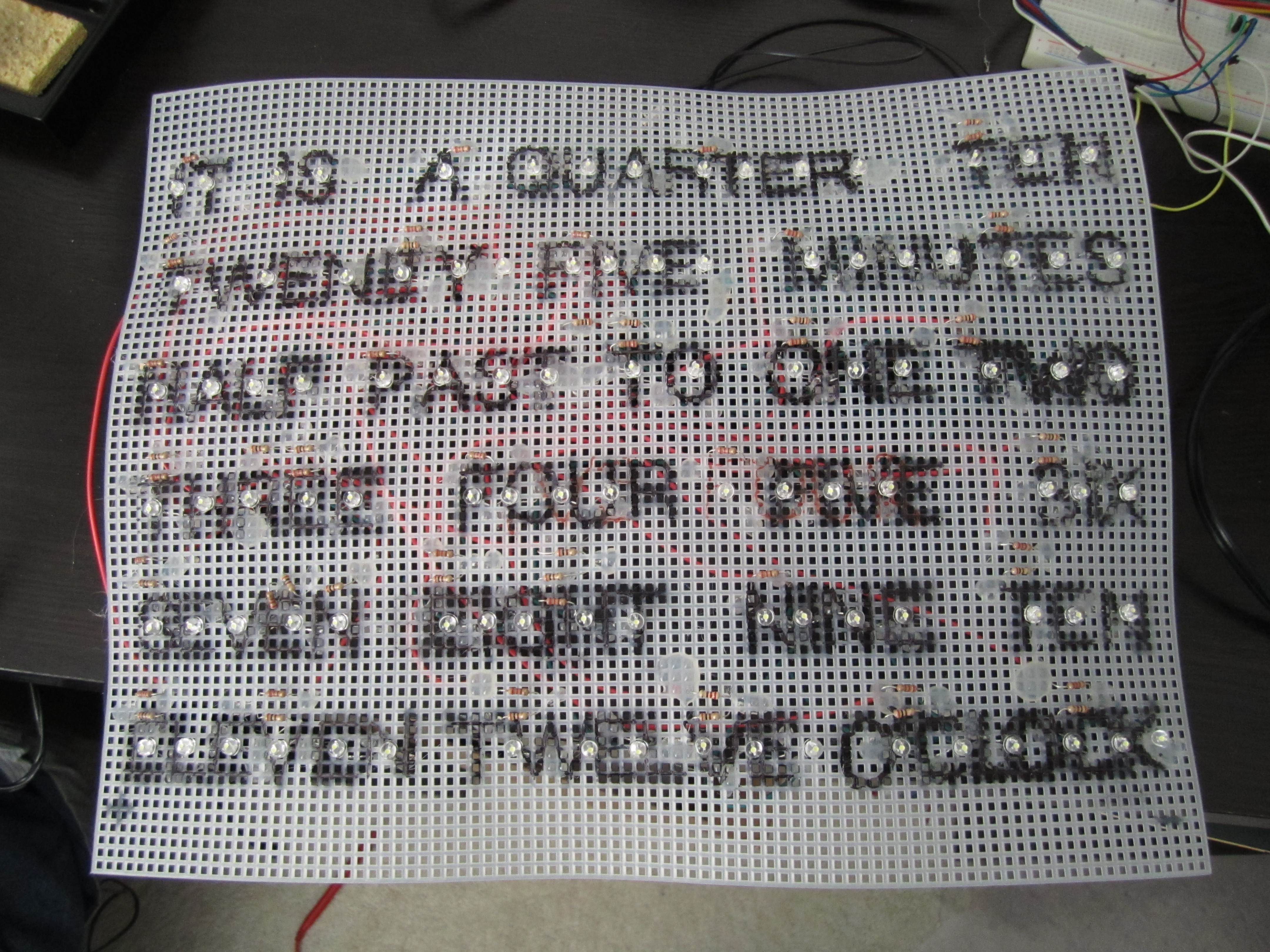
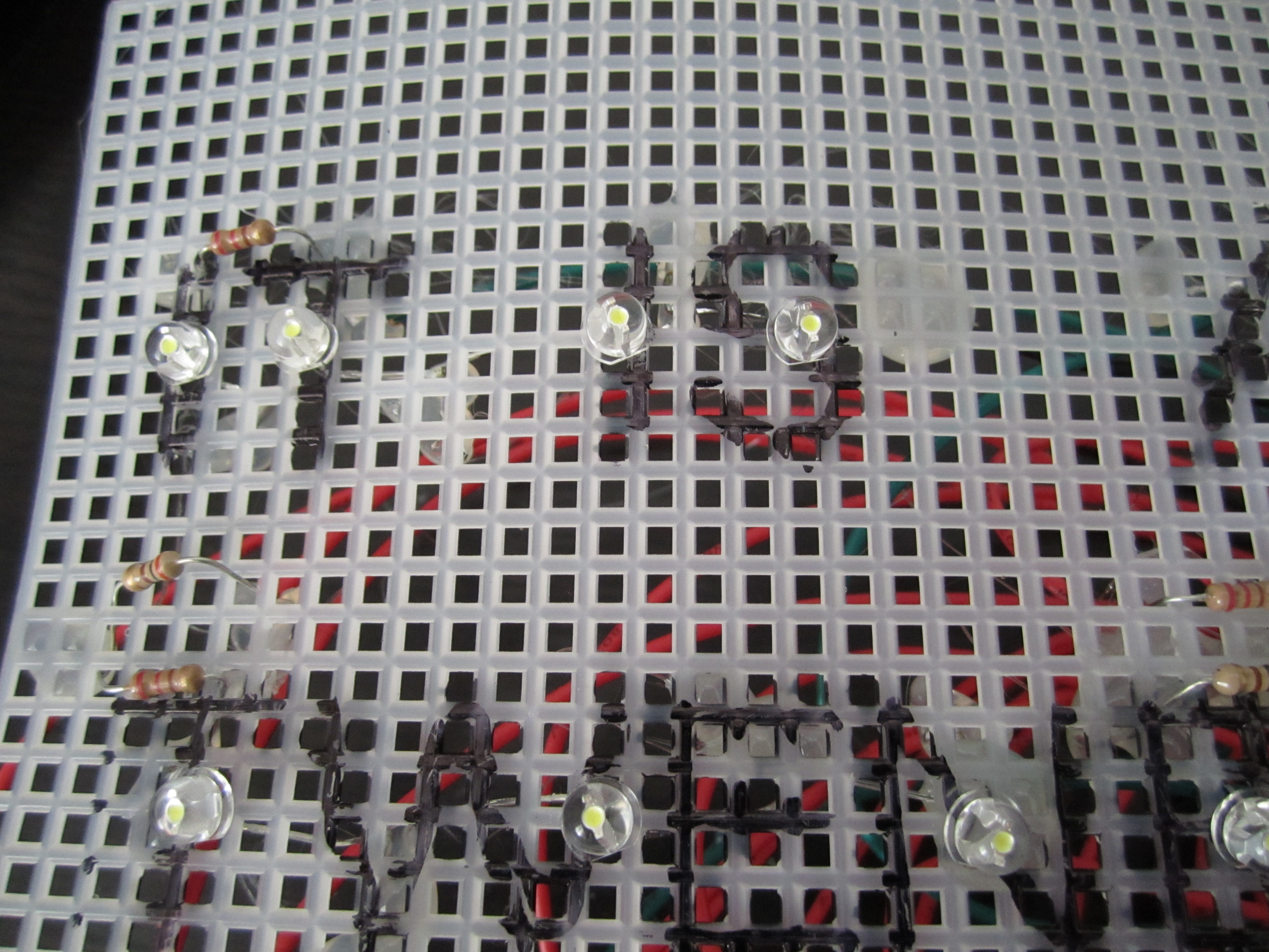
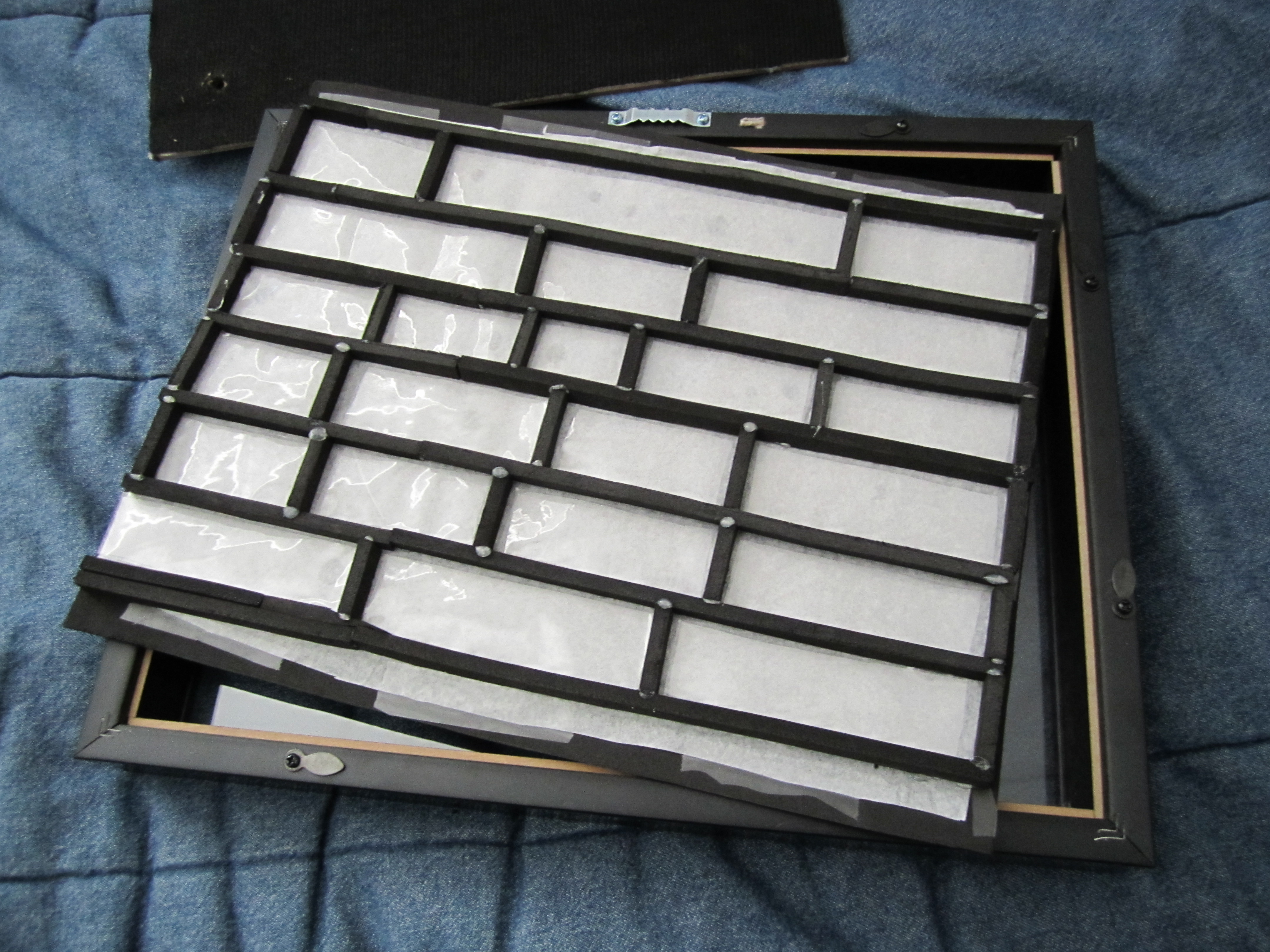
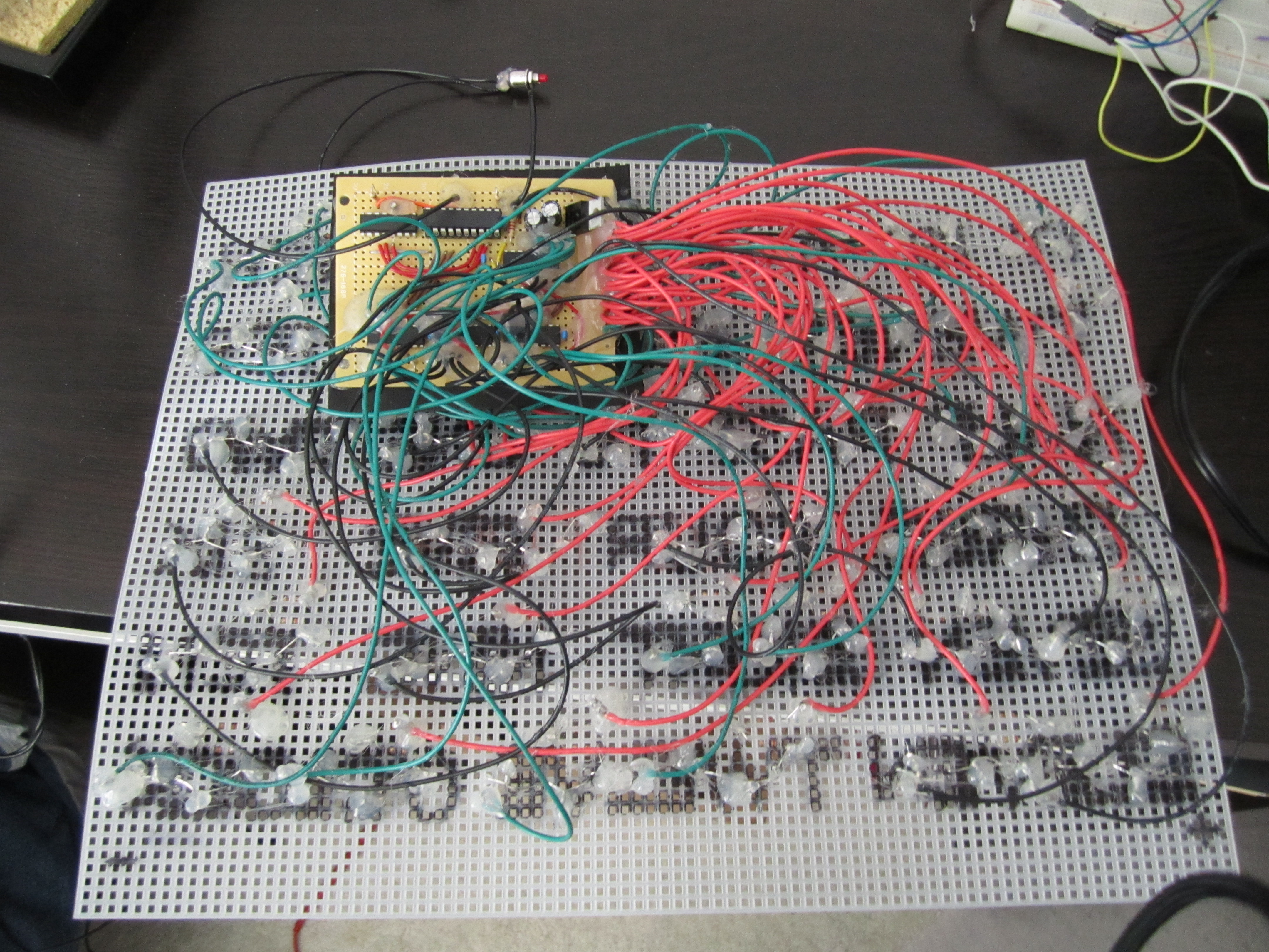
My sister and I built our own clone of Doug’s Word Clock as a holiday gift for our parents. It was my sister’s idea, but we split the work between the frontend and the backend. My sister put her hard-earned biochem PhD student skills to use in the craftsmanship of the frontend (just kidding; honestly, this was arguably some of the most time-consuming and frustrating work in this project.) She constructed the clockface out of black foam, flat tissue paper, plastic grid, packing tape, hot glue, and a picture frame. This also involved meticulously exacto’ing out every letter from the foam with a stencil. It turned out pretty well, with only minor light bleeding between the letters in the assembled clock. She was also responsible for threading/connecting the LEDs and resistors in the plastic grid.
For the backend, I went with my own design based on an Atmel AVR ATtiny2313, Maxim DS1305 RTC, four STMicro STP08DP05 LED shift register drivers, and Cree C535A Cool White LEDs. The schematic, bill of materials, commented code, and a high-level description of the firmware are available below.
A Note about LEDs
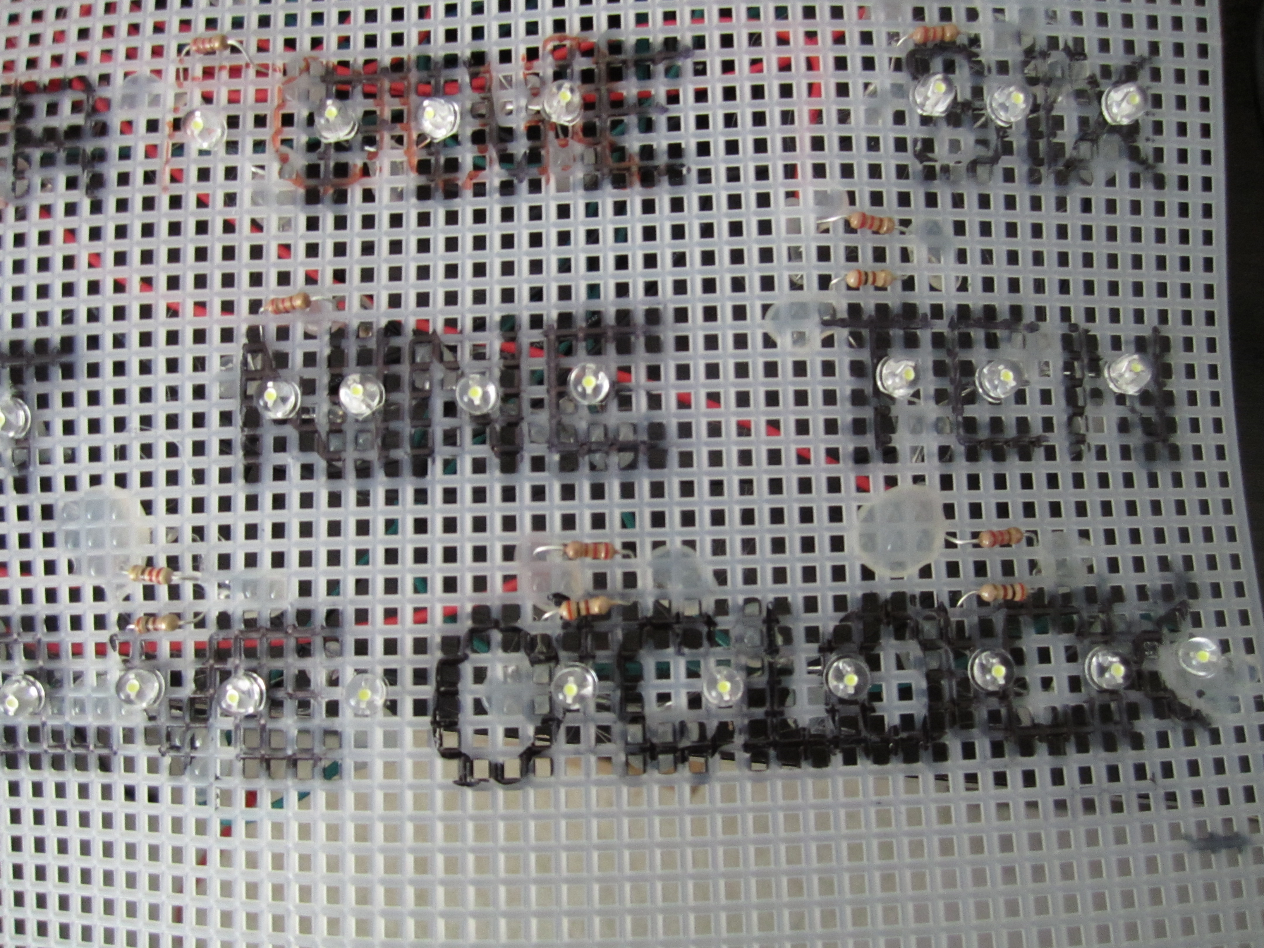
The Cree LEDs I picked are very bright (more quantitatively, they’re rated 1400mcd typical at 20mA) compared to the average off-the-shelf 5mm LED. I chose to run them at half their standard current, 10mA instead of 20mA, which still produces light bright enough to saturate my camera with vertical white lines and, more importantly, to light up each letter in the clockface. We went for one LED per letter, but we put the LEDs in strings, varying from 2 to 4 LEDs per string, in order to share the 32 total pins available from the four LED drivers (8 per driver).
For those interested in using similar LED drivers, working out how many LEDs per string you can sustain, which is a function of the forward voltage and power supply voltage, was the main bit of calculation in this project and drove the choice of power supply. At 10mA, the LED forward voltage is about 3V, so we went with a 15V power supply to fit up to 4 LEDs per string with some headroom. This allowed us to share all 99 LEDs among the 32 available driver pins. Also, in the extreme case that all 32 LED strings are on, there is 32 * 15 volts * 10 milliamperes = 4.8 Watts of power dissipated, so a 15V,1A (15W) power supply is plenty.
You might notice some resistors in series with the LED strings in the schematic. These aren’t for current limiting – the current is set by the REXT pin of the LED drivers and the LED drivers act as a constant current sink. Instead, these resistors are there to absorb some of the left over voltage drop of the 15V power supply in the 2 to 4 LED string and LED driver voltage loop, so the LED drivers aren’t responsible for dissipating all of that voltage slack at 10mA as heat. In other words, the resistors take up some of the power dissipation burden, so that the LED drivers don’t have to.
Schematic
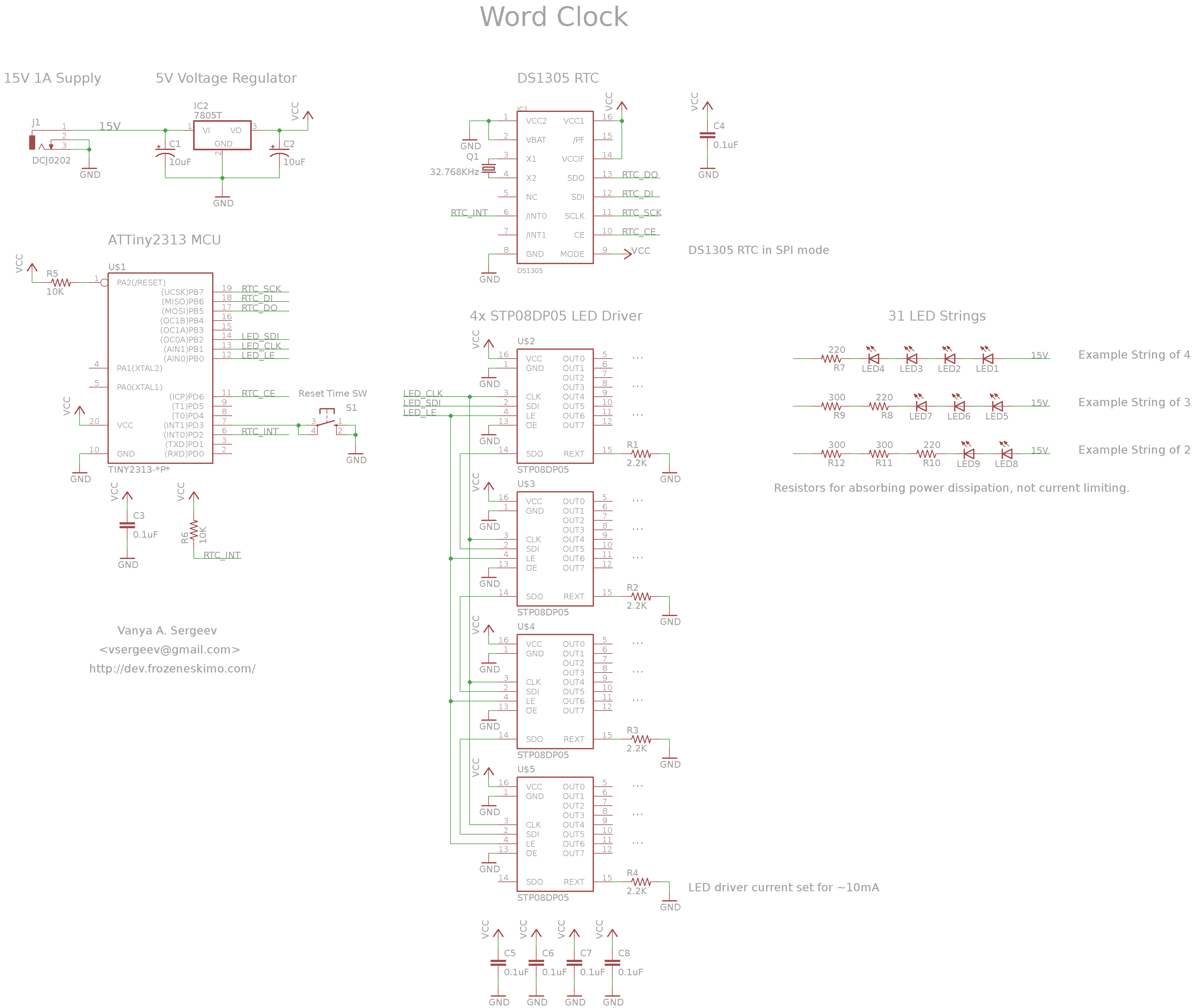 |
Download the EAGLE schematic here: wclock.sch
Bill of Materials
| Name | Digi-Key PN | Price x Qty |
|---|---|---|
| ATtiny2313 | ATTINY2313A-PU-ND | $2.58 x 1 |
| DS1305 | DS1305+-ND | $5.42 x 1 |
| 32.768kHz Crystal | 535-9032-ND | $0.25 x 1 |
| STP08DP05 LED Drivers | 497-6271-5-ND | $1.77 x 4 |
| 7805 Voltage Regulator | KA7805ETU-ND | $0.65 x 1 |
| Power Jack | CP-037A-ND | $0.91 x 1 |
| 15V 1A Power Supply | T992-P5P-ND | $10.80 x 1 |
| Cree C535A White LEDs | C535A-WJN-CS0V0151-ND | $0.19 x 99 |
| 220 ohm resistors | 30 | |
| 300 ohm resistors | 30 | |
| 2.2K ohm resistors | 4 | |
| 10K ohm resistors | 2 | |
| 10uF capacitors | 2 | |
| 0.1uF capacitors | 6 | |
| Total | ~$50.00 |
Code
I chose to write the firmware in AVR assembly for kicks (it was winter break after all). The microcontroller is asleep for most of the time, waking up only for interrupt 0, which is driven by the DS1305 RTC every minute, or for interrupt 1, which is triggered by a push button to reset the time to 12:00:00am (this is the time setting mechanism of the clock). The interrupt 0 handler reads the current time from the DS1305, rounds it down to 5 minutes intervals, does some math to index into an LED configuration table in flash, fetches the 32-bit LED configuration, and clocks it out to the four LED shift register drivers.
A small python script, gen_wclock_table.py, generates the LED configuration table based on the the LED string bit positions (arbitrarily) assigned across the four LED shift register drivers.
The firmware code is available in the git repository here: main.S, and is reproduced below. The entire firmware comes out to 1020 bytes, of which 576 bytes is the LED configuration table.
; Word Clock
; Idea from Doug's Word Clock - http://www.dougswordclock.com/
;
; Hardware: ATTiny2313 + DS1305 RTC + 4x STP08DP05 LED Driver
; Vanya A. Sergeev - vsergeev at gmail dot com
;

#define __AVR_ATtiny2313A__
#include <avr/io.h>

; I/O Definitions for LED Driver and RTC

#define LED_PORT	0x018
#define LED_DDR		0x017
#define LED_LE		0
#define	LED_CLK		1
#define LED_SDI		2

#define RTC_PORT	0x012
#define RTC_DDR		0x011
#define RTC_CE		6
#define RTC_INT		2
#define RTC_SW_INT	3

#define RTC_SPI_PORT	0x018
#define RTC_SPI_DDR	0x017

#define RTC_SPI_CLK	7
#define RTC_SPI_DO	6
#define RTC_SPI_DI	5


#define IO_USICR	0x00D
#define IO_USISR	0x00E
#define IO_USIDR	0x00F

;;; Vector table
.org 0x0000
vectors:
	rjmp reset
	rjmp int0_isr
	rjmp int1_isr
	rjmp reset
	rjmp reset
	rjmp reset
	rjmp reset
	rjmp reset
	rjmp reset
	rjmp reset
	rjmp reset
	rjmp reset
	rjmp reset
	rjmp reset
	rjmp reset
	rjmp reset
	rjmp reset
	rjmp reset
	rjmp reset


;;; Interrupt 0 Handler, driven by DS1305 RTC every minute.
int0_isr:
	; Acknowledge the interrupt by reading an alarm 0 register
	ldi r16, 0x0A
	rcall ds1305_reg_read

	; Read in the current minute
	ldi r16, 0x01
	rcall ds1305_reg_read
	; Convert from BCD to binary, save in r17
	andi r16, 0x7F
	rcall bcd_to_bin
	mov r17, r16

	; Read in the current hour
	ldi r16, 0x02
	rcall ds1305_reg_read
	; Convert from BCD to binary, save in r18
	andi r16, 0x1F
	rcall bcd_to_bin
	mov r18, r16
	; Decrement hours by 1, to have an index 0-11
	dec r18

	; Round minute down to five minutes, save in r19
	clr r19
	cpi r17, 5
	brlo .convert_five_done
	.convert_five_loop:
		inc r19
		subi r17, 5
		cpi r17, 5
		brsh .convert_five_loop
	.convert_five_done:

	; Compute the address into the LED time table

	; Initialize ZH:ZL = address of LED time table
	ldi r31, hi8(led_time_table)
	ldi r30, lo8(led_time_table)

	; Table Offset = ((Hours * 12) + (Five Minutes)) << 2

	; Convert hour to a hour table offset (soft multiply r18 by 12)
	; Clear destination r29:r28
	clr r29
	clr r28
	; Clear r16 and add r18, to set Z flag
	clr r16
	add r16, r18
	.multiply_by_12:
		breq .multiply_by_12_done
		adiw r28, 12
		dec r16
		rjmp .multiply_by_12
	.multiply_by_12_done:

	; Add minutes to get a hour-five minutes table offset
	clr r16
	add r28, r19
	adc r29, r16
	; Left shift twice to get a hour-five minutes-four byte table offset
	lsl r29
	lsl r28
	adc r29, r16
	lsl r29
	lsl r28
	adc r29, r16
	; Add the table offset to our Z pointer
	add r30, r28
	adc r31, r16
	add r31, r29

	; Read the LED configuration from the table and update LEDs
	lpm r16, Z+
	lpm r17, Z+
	lpm r18, Z+
	lpm r19, Z+
	rcall led_update

	reti


;;; Interrupt 1 Handler, driven by time reset push button.
int1_isr:
	; Re-initialize the DS1305 RTC, resetting the time to 12am
	rcall ds1305_init

	; Delay for debouncing
	rcall longdelay

	; Update the display and reti
	rjmp int0_isr


;;; Reset Handler
reset:
	; Set up stack pointer
	ldi r16, lo8(RAMEND)
	out 0x3D, r16

	; Initialize GPIO DDR for LED Drivers
	sbi LED_DDR, LED_CLK
	sbi LED_DDR, LED_SDI
	sbi LED_DDR, LED_LE

	; Initialize GPIO DDR for DS1305 RTC
	sbi RTC_DDR, RTC_CE
	cbi RTC_DDR, RTC_INT
	cbi RTC_DDR, RTC_SW_INT
	; Enable internal pull-up for time reset pull-down switch
	sbi RTC_PORT, RTC_SW_INT

	; Set up interrupts
	; Set interrupt 0 as falling-edge, interrupt 1 as falling-edge, set
	; sleep mode to idle, set sleep enable
	ldi r16, (1<<SE)|(1<<ISC01)|(1<<ISC11)
	sts MCUCR, r16
	; Enable interrupt 0 and interrupt 1 in general interrupt mask
	ldi r16, (1<<INT0)|(1<<INT1)
	sts GIMSK, r16

	; Disable analog comparator for power savings
	ldi r16, 0x80
	sts ACSR, r16

	; Clear the LED driver port
	clr r16
	out LED_PORT, r16

	; Initialize SPI IO for DS1305 RTC
	sbi RTC_SPI_DDR, RTC_SPI_CLK
	sbi RTC_SPI_DDR, RTC_SPI_DO
	cbi RTC_SPI_DDR, RTC_SPI_DI

	;;; Wait to make sure everything else has powered up...
	; The switching power supply I'm using has a slow start-up, and the AVR
	; turns on before some of the other ICs... A reset supervisor might be
	; more appropriate here.
	; Delay for ~8s
	rcall longdelay
	rcall longdelay
	rcall longdelay
	rcall longdelay
	rcall longdelay

	; Initialize LED state to off
	clr r16
	clr r17
	clr r18
	clr r19
	rcall led_update

	; Initialize the DS1305 RTC
	rcall ds1305_init

	; Setup the initial time LED state
	rcall int0_isr

	; Enable interrupts
	sei

	; Sleep
sleep_loop:
	sleep
	rjmp sleep_loop

;;;;;;;;;;;;;;;;;;;;;;;;;;;;;;;;;;;;;;;;;;;;;;;;;;;;;;;;;;;;
;;;;; DS1305 RTC Driver
;;;;;;;;;;;;;;;;;;;;;;;;;;;;;;;;;;;;;;;;;;;;;;;;;;;;;;;;;;;;

;;; Initialize the DS1305 RTC
ds1305_init:
	; Enable oscillator and disable write protect
	; Control register = 0x00
	ldi r16, 0x8F
	ldi r17, 0x00
	rcall ds1305_reg_write

	; Set time to 12:00:00 am
	; Hours = 12 am
	ldi r16, 0x82
	ldi r17, 0b01010010
	rcall ds1305_reg_write
	; Minutes = 00
	ldi r16, 0x81
	ldi r17, 0x00
	rcall ds1305_reg_write
	; Seconds = 00
	ldi r16, 0x80
	ldi r17, 0x00
	rcall ds1305_reg_write

	; Set up alarm 0 for every minute
	; Days = 0x80
	ldi r16, 0x8A
	ldi r17, 0x80
	rcall ds1305_reg_write
	; Hours = 0x80
	ldi r16, 0x89
	ldi r17, 0x80
	rcall ds1305_reg_write
	; Minutes = 0x80
	ldi r16, 0x88
	ldi r17, 0x80
	rcall ds1305_reg_write
	; Seconds = 0x00
	ldi r16, 0x87
	ldi r17, 0x00
	rcall ds1305_reg_write

	; Enable the Alarm 0 interrupt
	; Control register = (1<<INTCN)|(1<<AIE0)
	ldi r16, 0x8F
	ldi r17, 0b00000101
	rcall ds1305_reg_write

	ret

;;; Read a DS1305 Register
;;; Address passed in r16,
;;; Data returned in r16.
ds1305_reg_read:
	; Chip select
	sbi RTC_PORT, RTC_CE

	; Transmit address
	rcall spi_transfer
	; Transmit dummy, read data into r16
	ldi r16, 0xFF
	rcall spi_transfer

	; Chip deselect
	cbi RTC_PORT, RTC_CE
	ret

;;; Write an DS1305 Register
;;; Address passed in r16, Data passed in r17
ds1305_reg_write:
	; Chip select
	sbi RTC_PORT, RTC_CE

	; Transmit address
	rcall spi_transfer
	; Transmit data
	mov r16, r17
	rcall spi_transfer

	; Chip deselect
	cbi RTC_PORT, RTC_CE
	ret

;;; Shift out and in 8-bits through USI
;;; Data to shift out passed in r16,
;;; Data shifted in returned in r16.
spi_transfer:
	; Load the data into USI shift register
	out IO_USIDR, r16
	; Clear the current USI overflow status and counter
	ldi r16, (1<<USIOIF)
	out IO_USISR, r16
	; Select 3-wire mode, software clock, toggle clock
	ldi r16, 0b00011011

	; Wait for 8-bits to shift
	.clocking_wait:
		; Toggle the clock, shifting a bit and incrementing the counter
		out IO_USICR, r16
		nop
		nop
		nop
		nop
		; Check if 8-bits have been shifted
		sbis IO_USISR, USIOIF
		rjmp .clocking_wait

	; Copy the data shifted in to r16
	in r16, IO_USIDR
	ret

;;;;;;;;;;;;;;;;;;;;;;;;;;;;;;;;;;;;;;;;;;;;;;;;;;;;;;;;;;;;
;;;;; LED Driver STP08DP05
;;;;;;;;;;;;;;;;;;;;;;;;;;;;;;;;;;;;;;;;;;;;;;;;;;;;;;;;;;;;

;;; Update LED Driver Shift Registers
;;; Four bytes passed in r16, r17, r18, r19.
led_update:
	; Save r0 and r1 used by led_shift
	push r0
	push r1

	; Shift out all four bytes
	rcall led_shift
	mov r16, r17
	rcall led_shift
	mov r16, r18
	rcall led_shift
	mov r16, r19
	rcall led_shift

	; Strobe LE
	sbi LED_PORT, LED_LE
	nop
	cbi LED_PORT, LED_LE

	; Restore r0 and r1
	pop r1
	pop r0
	ret

; Helper function for led_update to shift out a byte and strobe CLK
; Byte to be shifted passed in r16.
; r0 and r1 are clobbered.
led_shift:
	; Save data in r0
	mov r0, r16
	; Initialize bit counter in r1
	ldi r16, 0x08
	mov r1, r16

	.led_bit_loop:
		; Shift next bit into carry
		lsl r0
		; Branch set up SDI accordingly
		brcc .led_bit_set0

		; Set SDI high
		.led_bit_set1:
			sbi LED_PORT, LED_SDI
			rjmp .led_clk_strobe

		; Set SDI low
		.led_bit_set0:
			cbi LED_PORT, LED_SDI

		; Strobe CLK
		.led_clk_strobe:
			sbi LED_PORT, LED_CLK
			cbi LED_PORT, LED_CLK

		dec r1
		brne .led_bit_loop
	ret

;;;;;;;;;;;;;;;;;;;;;;;;;;;;;;;;;;;;;;;;;;;;;;;;;;;;;;;;;;;;
;;;;; Misc
;;;;;;;;;;;;;;;;;;;;;;;;;;;;;;;;;;;;;;;;;;;;;;;;;;;;;;;;;;;;

;;; Convert two-digit BCD number to binary
;;; BCD number passed in r16.
;;; Binary number returned in r16.
bcd_to_bin:
	push r17
	push r18

	; Save lower BCD digit in r17
	mov r17, r16
	andi r17, 0x0F

	; Leave upper BCD digit in r16
	lsr r16
	lsr r16
	lsr r16
	lsr r16
	breq .add_ten_done

	; Loop adding 10 to the lower digit
	ldi r18, 10
	.add_ten:
		add r17, r18
		dec r16
		brne .add_ten

	; Move the converted BCD number back to r16
	.add_ten_done:
	mov r16, r17

	pop r18
	pop r17
	ret

; Long software delay
longdelay:
	push r20
	push r21
	push r22

	ldi r20, 0xff

	.loop0:
		ldi r21, 0xff
		.loop1:
			ldi r22, 0x05
			.loop2:
				dec r22
				brne .loop2
			dec r21
			brne .loop1
		dec r20
		brne .loop0

	pop r22
	pop r21
	pop r20
	ret

;;;;;;;;;;;;;;;;;;;;;;;;;;;;;;;;;;;;;;;;;;;;;;;;;;;;;;;;;;;;
;;;;; LED Time Table
;;;;;;;;;;;;;;;;;;;;;;;;;;;;;;;;;;;;;;;;;;;;;;;;;;;;;;;;;;;;

; Generated with gen_wclock_table.py
led_time_table:
	.word 0x00C0, 0x0120	; 01:00:00  Offset: 0
	.word 0x00C0, 0x412B	; 01:05:00  Offset: 4
	.word 0x00C0, 0x092B	; 01:10:00  Offset: 8
	.word 0x00C0, 0x0728	; 01:15:00  Offset: 12
	.word 0x00C0, 0x312B	; 01:20:00  Offset: 16
	.word 0x00C0, 0x712B	; 01:25:00  Offset: 20
	.word 0x00C0, 0x012C	; 01:30:00  Offset: 24
	.word 0x00C0, 0x7153	; 01:35:00  Offset: 28
	.word 0x00C0, 0x3153	; 01:40:00  Offset: 32
	.word 0x00C0, 0x0750	; 01:45:00  Offset: 36
	.word 0x00C0, 0x0953	; 01:50:00  Offset: 40
	.word 0x00C0, 0x4153	; 01:55:00  Offset: 44
	.word 0x00C0, 0x0140	; 02:00:00  Offset: 48
	.word 0x00C0, 0x414B	; 02:05:00  Offset: 52
	.word 0x00C0, 0x094B	; 02:10:00  Offset: 56
	.word 0x00C0, 0x0748	; 02:15:00  Offset: 60
	.word 0x00C0, 0x314B	; 02:20:00  Offset: 64
	.word 0x00C0, 0x714B	; 02:25:00  Offset: 68
	.word 0x00C0, 0x014C	; 02:30:00  Offset: 72
	.word 0x01C0, 0x7193	; 02:35:00  Offset: 76
	.word 0x01C0, 0x3193	; 02:40:00  Offset: 80
	.word 0x01C0, 0x0790	; 02:45:00  Offset: 84
	.word 0x01C0, 0x0993	; 02:50:00  Offset: 88
	.word 0x01C0, 0x4193	; 02:55:00  Offset: 92
	.word 0x01C0, 0x0180	; 03:00:00  Offset: 96
	.word 0x01C0, 0x418B	; 03:05:00  Offset: 100
	.word 0x01C0, 0x098B	; 03:10:00  Offset: 104
	.word 0x01C0, 0x0788	; 03:15:00  Offset: 108
	.word 0x01C0, 0x318B	; 03:20:00  Offset: 112
	.word 0x01C0, 0x718B	; 03:25:00  Offset: 116
	.word 0x01C0, 0x018C	; 03:30:00  Offset: 120
	.word 0x04C0, 0x7113	; 03:35:00  Offset: 124
	.word 0x04C0, 0x3113	; 03:40:00  Offset: 128
	.word 0x04C0, 0x0710	; 03:45:00  Offset: 132
	.word 0x04C0, 0x0913	; 03:50:00  Offset: 136
	.word 0x04C0, 0x4113	; 03:55:00  Offset: 140
	.word 0x04C0, 0x0100	; 04:00:00  Offset: 144
	.word 0x04C0, 0x410B	; 04:05:00  Offset: 148
	.word 0x04C0, 0x090B	; 04:10:00  Offset: 152
	.word 0x04C0, 0x0708	; 04:15:00  Offset: 156
	.word 0x04C0, 0x310B	; 04:20:00  Offset: 160
	.word 0x04C0, 0x710B	; 04:25:00  Offset: 164
	.word 0x04C0, 0x010C	; 04:30:00  Offset: 168
	.word 0x02C0, 0x7113	; 04:35:00  Offset: 172
	.word 0x02C0, 0x3113	; 04:40:00  Offset: 176
	.word 0x02C0, 0x0710	; 04:45:00  Offset: 180
	.word 0x02C0, 0x0913	; 04:50:00  Offset: 184
	.word 0x02C0, 0x4113	; 04:55:00  Offset: 188
	.word 0x02C0, 0x0100	; 05:00:00  Offset: 192
	.word 0x02C0, 0x410B	; 05:05:00  Offset: 196
	.word 0x02C0, 0x090B	; 05:10:00  Offset: 200
	.word 0x02C0, 0x0708	; 05:15:00  Offset: 204
	.word 0x02C0, 0x310B	; 05:20:00  Offset: 208
	.word 0x02C0, 0x710B	; 05:25:00  Offset: 212
	.word 0x02C0, 0x010C	; 05:30:00  Offset: 216
	.word 0x08C0, 0x7113	; 05:35:00  Offset: 220
	.word 0x08C0, 0x3113	; 05:40:00  Offset: 224
	.word 0x08C0, 0x0710	; 05:45:00  Offset: 228
	.word 0x08C0, 0x0913	; 05:50:00  Offset: 232
	.word 0x08C0, 0x4113	; 05:55:00  Offset: 236
	.word 0x08C0, 0x0100	; 06:00:00  Offset: 240
	.word 0x08C0, 0x410B	; 06:05:00  Offset: 244
	.word 0x08C0, 0x090B	; 06:10:00  Offset: 248
	.word 0x08C0, 0x0708	; 06:15:00  Offset: 252
	.word 0x08C0, 0x310B	; 06:20:00  Offset: 256
	.word 0x08C0, 0x710B	; 06:25:00  Offset: 260
	.word 0x08C0, 0x010C	; 06:30:00  Offset: 264
	.word 0x30C0, 0x7113	; 06:35:00  Offset: 268
	.word 0x30C0, 0x3113	; 06:40:00  Offset: 272
	.word 0x30C0, 0x0710	; 06:45:00  Offset: 276
	.word 0x30C0, 0x0913	; 06:50:00  Offset: 280
	.word 0x30C0, 0x4113	; 06:55:00  Offset: 284
	.word 0x30C0, 0x0100	; 07:00:00  Offset: 288
	.word 0x30C0, 0x410B	; 07:05:00  Offset: 292
	.word 0x30C0, 0x090B	; 07:10:00  Offset: 296
	.word 0x30C0, 0x0708	; 07:15:00  Offset: 300
	.word 0x30C0, 0x310B	; 07:20:00  Offset: 304
	.word 0x30C0, 0x710B	; 07:25:00  Offset: 308
	.word 0x30C0, 0x010C	; 07:30:00  Offset: 312
	.word 0xC0C0, 0x7113	; 07:35:00  Offset: 316
	.word 0xC0C0, 0x3113	; 07:40:00  Offset: 320
	.word 0xC0C0, 0x0710	; 07:45:00  Offset: 324
	.word 0xC0C0, 0x0913	; 07:50:00  Offset: 328
	.word 0xC0C0, 0x4113	; 07:55:00  Offset: 332
	.word 0xC0C0, 0x0100	; 08:00:00  Offset: 336
	.word 0xC0C0, 0x410B	; 08:05:00  Offset: 340
	.word 0xC0C0, 0x090B	; 08:10:00  Offset: 344
	.word 0xC0C0, 0x0708	; 08:15:00  Offset: 348
	.word 0xC0C0, 0x310B	; 08:20:00  Offset: 352
	.word 0xC0C0, 0x710B	; 08:25:00  Offset: 356
	.word 0xC0C0, 0x010C	; 08:30:00  Offset: 360
	.word 0x00C1, 0x7113	; 08:35:00  Offset: 364
	.word 0x00C1, 0x3113	; 08:40:00  Offset: 368
	.word 0x00C1, 0x0710	; 08:45:00  Offset: 372
	.word 0x00C1, 0x0913	; 08:50:00  Offset: 376
	.word 0x00C1, 0x4113	; 08:55:00  Offset: 380
	.word 0x00C1, 0x0100	; 09:00:00  Offset: 384
	.word 0x00C1, 0x410B	; 09:05:00  Offset: 388
	.word 0x00C1, 0x090B	; 09:10:00  Offset: 392
	.word 0x00C1, 0x0708	; 09:15:00  Offset: 396
	.word 0x00C1, 0x310B	; 09:20:00  Offset: 400
	.word 0x00C1, 0x710B	; 09:25:00  Offset: 404
	.word 0x00C1, 0x010C	; 09:30:00  Offset: 408
	.word 0x00C2, 0x7113	; 09:35:00  Offset: 412
	.word 0x00C2, 0x3113	; 09:40:00  Offset: 416
	.word 0x00C2, 0x0710	; 09:45:00  Offset: 420
	.word 0x00C2, 0x0913	; 09:50:00  Offset: 424
	.word 0x00C2, 0x4113	; 09:55:00  Offset: 428
	.word 0x00C2, 0x0100	; 10:00:00  Offset: 432
	.word 0x00C2, 0x410B	; 10:05:00  Offset: 436
	.word 0x00C2, 0x090B	; 10:10:00  Offset: 440
	.word 0x00C2, 0x0708	; 10:15:00  Offset: 444
	.word 0x00C2, 0x310B	; 10:20:00  Offset: 448
	.word 0x00C2, 0x710B	; 10:25:00  Offset: 452
	.word 0x00C2, 0x010C	; 10:30:00  Offset: 456
	.word 0x00CC, 0x7113	; 10:35:00  Offset: 460
	.word 0x00CC, 0x3113	; 10:40:00  Offset: 464
	.word 0x00CC, 0x0710	; 10:45:00  Offset: 468
	.word 0x00CC, 0x0913	; 10:50:00  Offset: 472
	.word 0x00CC, 0x4113	; 10:55:00  Offset: 476
	.word 0x00CC, 0x0100	; 11:00:00  Offset: 480
	.word 0x00CC, 0x410B	; 11:05:00  Offset: 484
	.word 0x00CC, 0x090B	; 11:10:00  Offset: 488
	.word 0x00CC, 0x0708	; 11:15:00  Offset: 492
	.word 0x00CC, 0x310B	; 11:20:00  Offset: 496
	.word 0x00CC, 0x710B	; 11:25:00  Offset: 500
	.word 0x00CC, 0x010C	; 11:30:00  Offset: 504
	.word 0x00F0, 0x7113	; 11:35:00  Offset: 508
	.word 0x00F0, 0x3113	; 11:40:00  Offset: 512
	.word 0x00F0, 0x0710	; 11:45:00  Offset: 516
	.word 0x00F0, 0x0913	; 11:50:00  Offset: 520
	.word 0x00F0, 0x4113	; 11:55:00  Offset: 524
	.word 0x00F0, 0x0100	; 12:00:00  Offset: 528
	.word 0x00F0, 0x410B	; 12:05:00  Offset: 532
	.word 0x00F0, 0x090B	; 12:10:00  Offset: 536
	.word 0x00F0, 0x0708	; 12:15:00  Offset: 540
	.word 0x00F0, 0x310B	; 12:20:00  Offset: 544
	.word 0x00F0, 0x710B	; 12:25:00  Offset: 548
	.word 0x00F0, 0x010C	; 12:30:00  Offset: 552
	.word 0x00C0, 0x7133	; 12:35:00  Offset: 556
	.word 0x00C0, 0x3133	; 12:40:00  Offset: 560
	.word 0x00C0, 0x0730	; 12:45:00  Offset: 564
	.word 0x00C0, 0x0933	; 12:50:00  Offset: 568
	.word 0x00C0, 0x4133	; 12:55:00  Offset: 572