Wireless Power Meter
Project Date: 09/2009
Pictures
 |
 |
 |
|
 |
 |
 |
 |
Source
GitHub: https://github.com/vsergeev/wireless-power-meter
Description
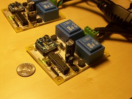
The Wireless Power Meter is a simplistic ATmega88p and ZigBee/XBee based true V-I power meter. AC voltage measurement is made from the rectified signal of a step-down transformer, and current measurement is made with the pass-through Allegro ACS712 Hall-Effect sensor. The microcontroller and wireless transceiver are magnetically and optically isolated from the high voltage power circuitry.
This project has some important issues and proposed solutions that are worth pointing out to anyone interested in building such a power meter:
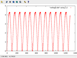
- The rectification for the voltage measurement signal isn’t perfect, as there is some clipping and loss in the diode full-wave bridge rectifier. After the step-down transformer, the signal should be sufficiently scaled for purely analog signal processing, so this clipping can be remedied by using an analog full-wave precision rectifier.
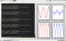
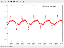
- Leaked magnetic flux from the circuit’s own power transformer influences the Allegro current sensor measurement, imposing a waveform based on the measurement circuit’s very own current load. I thought it would be neat if I could have the device powered by the same outlet that powered the appliance plugged into it, but I didn’t anticipate the E&M consequences of having that power supply on board next to the voltage measurement step-down transformer (doh!). This can be easily solved by moving the power supply for the device physically off of the board, i.e. just using an external wall wart. It could alternatively be solved by shielding, but that seems like messier business.
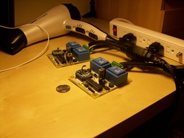
- Finally, this circuit is generally not safe, because of semi-exposed high voltage pads. It should really be put into an enclosure, at the very least. Please don’t repeat the hair dryer meter setup in the picture above.
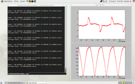
Lastly, I am worried about whether the voltage measurement step-down transformer has any significant parasitic reactive impedance (I’m not terribly familiar with the properties of real transformers) that could cause a phase shift between the actual voltage measurement and the scaled down one on the other side of the step-down transformer. This would be problematic, because very important power information (the power factor) is stored in the relative phase shift between the voltage and current waveforms. An unaccounted phase shift in the voltage waveform would contaminate this measurement.
I should also mention that the more common, commercially accepted way of making these sorts of power measurements seems to be an all-in-one “energy metering IC”. These chips effectively do everything measurement related for you, taking into account all sorts of second-order effects as well, and give you a digital interface to read the results. In application, the energy metering IC itself is typically not isolated from the power line, but the digital interface can be optocoupled, and so you can still isolate the digital data collection circuitry. Here are a few examples of energy metering ICs:
http://www.microchip.com/ParamChartSearch/chart.aspx?branchID=11029&mid=11&lang=en&pageId=79
http://www.nxp.com/products/microcontrollers/application_specific/EM773FHN33.html – this one is built into an ARM microcontroller!
The easiest path to a custom high-accuracy power meter would probably be a circuit centered around one of those energy metering ICs.
Schematic
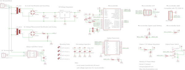 |
Download the EAGLE schematic here: wireless_power_meter.sch
Board
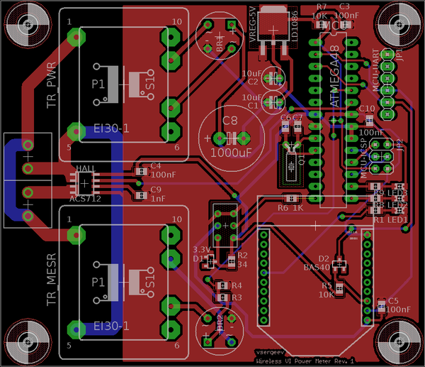 |
Download the EAGLE layout here: wireless_power_meter.brd
