Wireless TRIAC
Project Date: 09/2009
Source
GitHub: https://github.com/vsergeev/wireless-triac
Schematic
 |
Download the EAGLE schematic here: wireless_triac.sch
Board
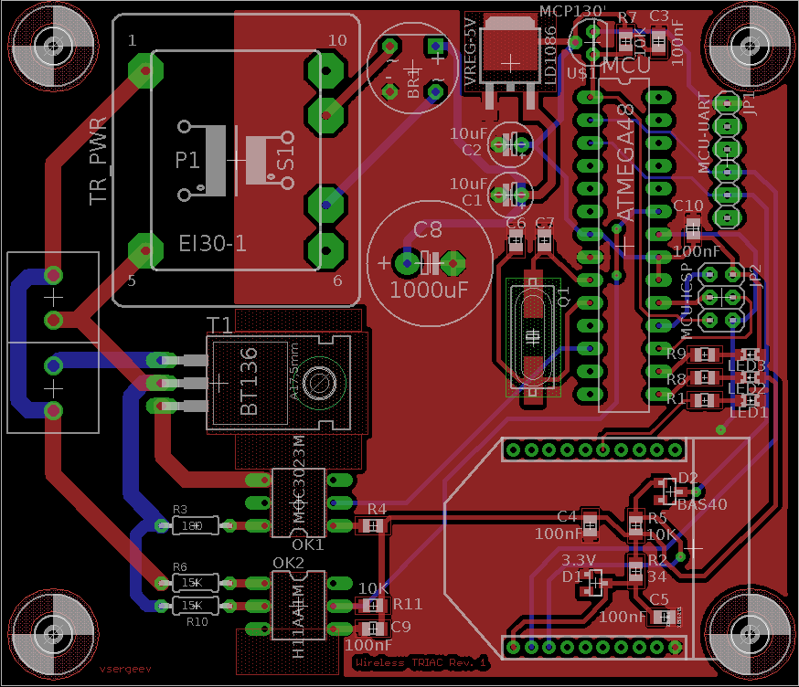 |
Download the EAGLE layout here: wireless_triac.brd
Bill of Materials
| Qty | Digi-key Part Number | Customer Reference |
|---|---|---|
| 4 | 497-4239-1-ND | VREG-5V |
| 10 | 493-1372-ND | C1,C2 |
| 20 | 478-3351-1-ND | C3,C4,C5,C9,C10 |
| 4 | 565-1311-ND | C8 |
| 4 | 568-1675-1-ND | D1 |
| 4 | BAS40TPMSCT-ND | D2 |
| 10 | 160-1179-1-ND | LED1,LED2,LED3 |
| 10 | RHM402CRCT-ND | R8,R9 |
| 10 | RHM180CRCT-ND | R1 |
| 20 | RMCF0805JT10K0CT-ND | R4,R5,R7,R11 |
| 10 | RNCP0805FTD33R2CT-ND | R2 |
| 8 | 15KW-1-ND | R6,R10 |
| 1 | SAM1035-50-ND | JP1,JP2 |
| 4 | 535-10232-1-ND | Q1 |
| 10 | 709-1171-1-ND | C6,C7 |
| 5 | W04GDI-ND | BR1 |
| 4 | MCP130-475DI/TO-ND | U1 |
| 4 | ATMEGA48P-20PU-ND | MCU |
| 5 | 180W-1-ND | R3 |
| 4 | 3M5480-ND | MCU |
| 4 | MOC3023MFS-ND | OK1 |
| 4 | H11AA1M-ND | OK2 |
| 4 | 568-3651-5-ND | T1 |
| 8 | S5751-10-ND | XBee |
| 3 | 567-1025-5-ND | TR_PWR |
| 4 | A98081-ND | T_IN,T_OUT |
| 3 | 602-1098-ND | XBEE |
Qty, Digi-key Part Number, Customer Reference
4,497-4239-1-ND,VREG-5V
10,493-1372-ND,C1,C2
20,478-3351-1-ND,C3,C4,C5,C9,C10
4,565-1311-ND,C8
4,568-1675-1-ND,D1
4,BAS40TPMSCT-ND,D2
10,160-1179-1-ND,LED1,LED2,LED3
10,RHM402CRCT-ND,R8,R9
10,RHM180CRCT-ND,R1
20,RMCF0805JT10K0CT-ND,R4,R5,R7,R11
10,RNCP0805FTD33R2CT-ND,R2
8,15KW-1-ND,R6,R10
1,SAM1035-50-ND,JP1,JP2
4,535-10232-1-ND,Q1
10,709-1171-1-ND,C6,C7
5,W04GDI-ND,BR1
4,MCP130-475DI/TO-ND,U1
4,ATMEGA48P-20PU-ND,MCU
5,180W-1-ND,R3
4,3M5480-ND,MCU
4,MOC3023MFS-ND,OK1
4,H11AA1M-ND,OK2
4,568-3651-5-ND,T1
8,S5751-10-ND,XBee
3,567-1025-5-ND,TR_PWR
4,A98081-ND,T_IN,T_OUT
3,602-1098-ND,XBEE
Description
This project was used as a wireless light dimmer, but in principle can be used to dim resistive loads and wirelessly turn on/off loads. The current code includes a routine to dim a light bulb in a “heartbeat” pattern, with the heartbeat frequency remotely adjustable.
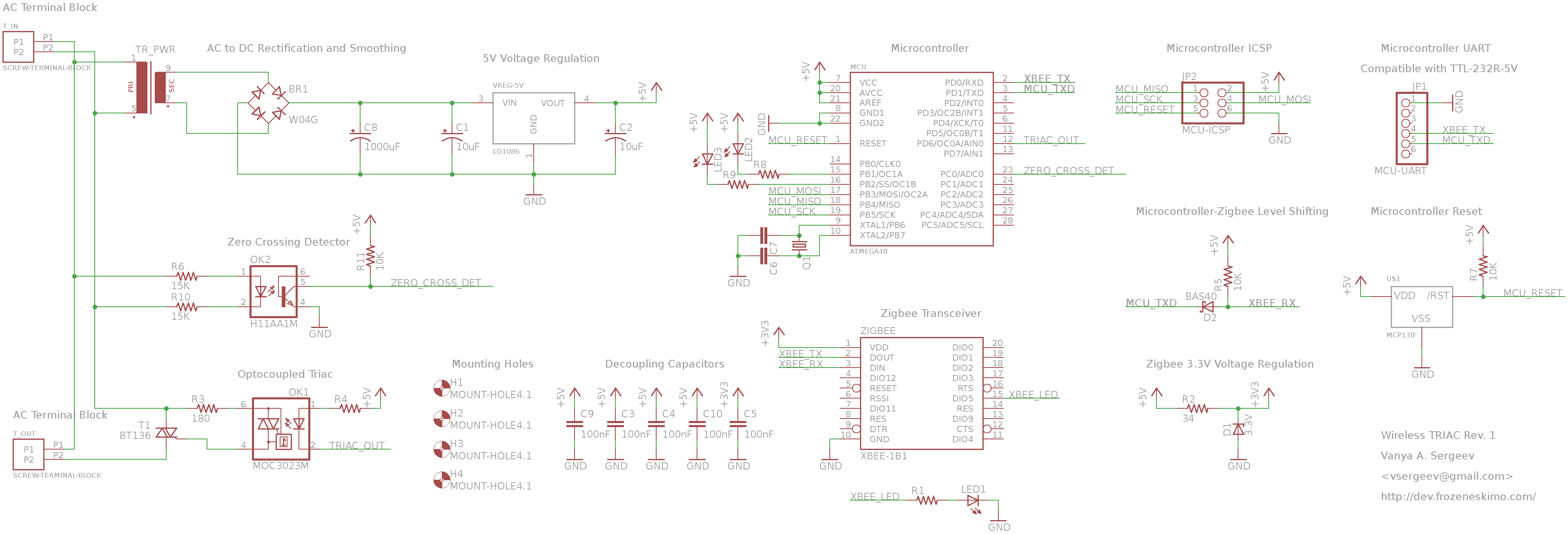
The top left of the schematic shows the wall outlet (US 120VAC) being stepped down with a small transformer, then full rectified and regulated. This powers the entire board from the wall. The top right shows a microcontroller, ATmega48, its programming header, and a UART connection to the microcontroller (for debugging). The bottom right shows the XBee and its basic voltage regulation (it’s 3.3V), as well as an LED that indicates when the XBee is connected.
The bottom left is the zero crossing detector and the TRIACs. I’m going to go ahead and explain this approach for light dimming, so please bear with me if you are already familiar with all of this. It involves two components: the TRIAC, and the zero crossing detector.
The first key component is the TRIAC. There are actually two TRIACs. The one on the right, MOC3023M, is a smaller opto-isolated triac, which isn’t rated for the current to drive a typical wall outlet load, but can be used to turn on the bigger TRIAC, the BT136. The bigger TRIAC is in series with the load, so when the opto-coupled TRIAC is turned on, and subsequently the bigger TRIAC is turned on, the load will received power from the wall outlet.
The thing about TRIACs is that when they turn on, they stay on until the voltage across them falls to a threshold (near zero). Then they turn off – and this is intrinsic to the device. If you turn on the TRIACs at the beginning of a half cycle, they will stay on until the end of the half cycle (wall voltage hits approximately zero). To continue allowing power to the load, you have to turn the TRIACs back on on the next half cycle.
So if you want to allow full power to the load, that means that you just need to turn on the TRIAC on every single half cycle, which is marked by a zero crossing in the wall voltage. This is where the zero crossing detector comes in…
The zero crossing detector gives an indication of when the AC wall voltage is at zero. It’s implemented with a simpler opto-coupler. Please note that the part used in this circuit is the H11AA1M (two A’s)! NOT the H11A1M (one A). The H11A1M will explode in this configuration. The reason for this is that H11A1M is a DC optocoupler that has a single LED (which is pictured in the schematic). You cannot reverse bias this DC LED more than 6V (and the US wall outlet goes up to 170V).
The H11AA1M on the other hand, has two LEDs in parallel, and wired in opposite directions. This means that if you apply an AC signal, when it’s positive, one of the LEDs will light up, and when it’s negative, the other LED will light up (shunting the current so that the other LED is safe). But, both H11AA1M and H11A1M parts have identical pinouts, so the same schematic symbol and footprint works (I believe Eagle only had the H11A1M, so I had just used that one).
SAs you can imagine, as the wall outlet’s 120VAC (170V peak) is oscillating at 60Hz, the LED will be on for pretty much positive 1.17V to 170V, as well as negative 1.17V to 170V (the 1.17V is the forward voltage). When the LED is on, the transistor on the right hand side of the isolation is also on, and it pulls the ZERO_CROSS_DET signal low, so the microcontroller just sees a 0 on this pin. When the LED is off, which corresponds to when the wall voltage is roughly zero, the LED will turn off, so the transistor will turn off, and the ZERO_CROSS_DET signal will be pulled up high by R11. The microcontroller sees a short 1 pulse, which corresponds to a zero crossing in the wall voltage.
So back to the big picture. To deliver full power to the load, the microcontroller simply needs to pull TRIAC_OUT low every time it sees a pulse on ZERO_CROSS_DET, to turn on the TRIACs at the beginning of every half cycle.
With this functionality in place, dimming is simple. Dimming is simply delivering less than full power to the load on every half cycle. So if you wanted to dim it 50%, that means that you would wait for the ZERO_CROSS_DET pulse (marking the start of a half cycle), then wait 50% * 1/(2*60Hz) = 4.17ms after that moment, then pull TRIAC_OUT low to turn on the triac. The triac will conduct for the second half of the AC half cycle and then turn off. If you do this for every half cycle, the load will only be on for half the time, effectively dimming it 50%. If you want to dim 30%, simply wait until 70% * 1/(2*60Hz) = 5.83ms to turn on the triac.
The code is currently configured to convey a “heartbeat” (dim up, dim down, which appears more like breathing) with an adjustable beat speed. So right now, the only information sent over the XBee is the speed of the heartbeat, not for example, a dimming percentage value. However this can easily be modified for more general purpose dimming – in fact the functionality is all coded there, if you see the test code.
I should note that this is meant for purely resistive loads, e.g. incandescent light bulbs. If the load is inductive, then when the TRIAC turns off there will be an inductive kick/spark across the TRIAC, which could potentially damage it. In this case, there needs to be a snubber across the TRIAC, like a resistor and capacitor in parallel with the triac (see pages 6-7 in MOC3023M datasheet).
This project works great with incandescent bulbs or similar resistive bulb technology. LED bulbs that hook up to the wall / incandescent bulb sockets should also be ok. Fluorescent bulbs that fit inside incandescent bulb sockets probably shouldn’t and can’t be dimmed because they may have some significant start up time (and it might be especially bad for it, if the bulb is retarted every time). Pure fluorescent bulbs on their own require a lamp ballast, and must be dimmed by the lamp ballast. Raw LEDs need to be dimmed with PWM.
